
Multi-deposition-chamber CVI (chemical vapor infiltration) device for compacting carbon/carbon crucible and method using same

A deposition chamber and densification technology, applied in the field of carbon/carbon crucible material preparation for single crystal silicon furnace, can solve the problems of large vertical density difference, low production efficiency, low densification efficiency, etc. Simple structure and uniform density

Active Publication Date: 2012-05-02
XIAN CHAOMA SCI TECH
View PDF6 Cites 10 Cited by
  • Summary
  • Abstract
  • Description
  • Claims
  • Application Information

AI Technical Summary

Problems solved by technology

[0005] The carbon / charcoal crucible preparation process disclosed in the above two patent application documents all has the following disadvantages and deficiencies: first, the amount of furnace loading is small, the equipment capacity is low, and the production efficiency is low; The height can reach 2400mm~4800mm, and the air can only be fed from the bottom of the furnace. First, it contacts with the first layer of crucible prefabricated body, and pyrolysis carbon deposition reaction occurs. There are many products with large molecular weight in the residual gas, and the deposition effect is poor. The difference is very large, up to more than double; third, the flow rate of propylene or natural gas carbon source gas is small, the weight gain is small, and the compaction efficiency is low

Method used


Image

  • Multi-deposition-chamber CVI (chemical vapor infiltration) device for compacting carbon/carbon crucible and method using same
  • Multi-deposition-chamber CVI (chemical vapor infiltration) device for compacting carbon/carbon crucible and method using same

Examples


Embodiment 1

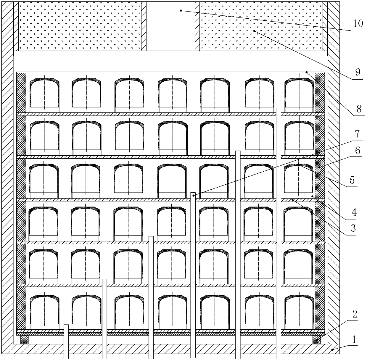
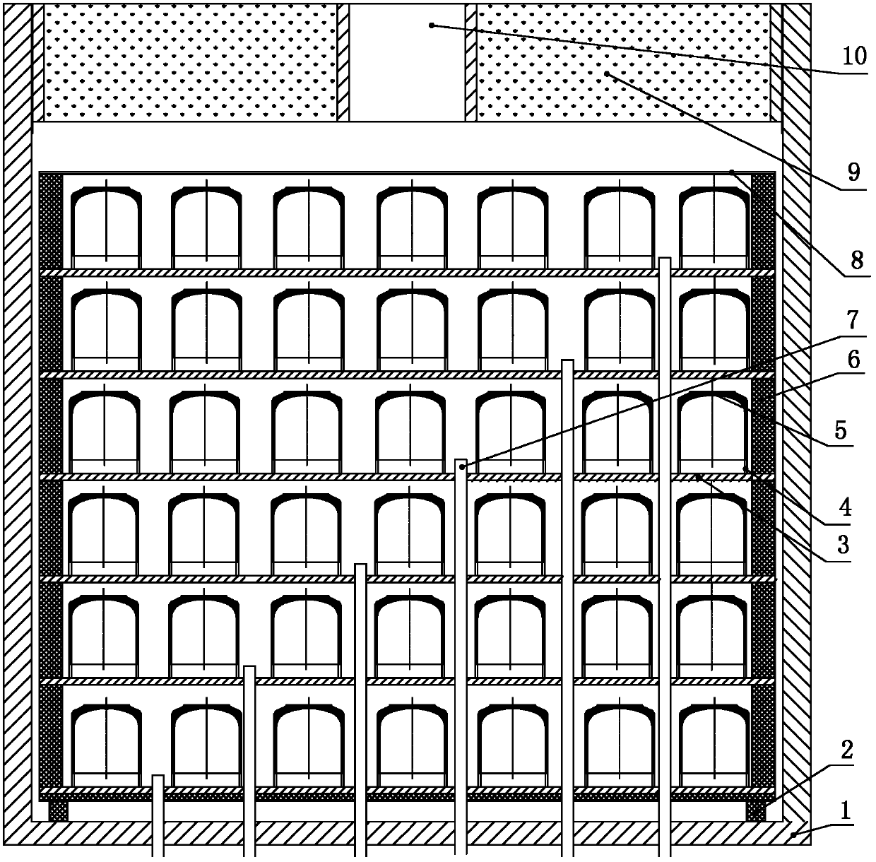
[0037] Such as figure 1 The shown multi-deposition chamber CVI dense carbon / carbon crucible device includes a chemical vapor deposition furnace composed of a furnace outer tank and a furnace inner tank 1, and also includes a bottom-to-top arrangement in the furnace inner tank 1 and is arranged horizontally The multi-layer graphite separator 3, a plurality of intake pipes 7 inserted into the furnace tank 1 from bottom to top and the furnace cover 9 sealed and installed on the furnace tank 1, between the graphite separators 3 of two adjacent layers They are all separated by a plurality of graphite support columns 6 arranged vertically, and the plurality of graphite support columns 6 are arranged along the outer edge line of the graphite separator 3 . The inner bottom of the furnace tank 1 is provided with a graphite support 2 for horizontal laying of the graphite separator 3 at the bottom, and the graphite support 2 is arranged horizontally. The multiple layers of graphite sepa...

Embodiment 2

[0061] In this embodiment, the device of the multi-deposition chamber CVI dense carbon / carbon crucible is different from Embodiment 1 in that: the number of the deposition chambers is 7, and 7 dense carbon / carbon crucibles are placed on each deposition chamber Prefabricated body 5, the number of the inlet pipe 7 is 7 and its diameter is Φ20mm, the height of the inlet pipe 7 inserted into the deposition chamber is 30mm, the inner diameter of the carbon / carbon composite ring plate is 1500mm, the outer Diameter is 2500mm and its thickness is 60mm, and the outer diameter of graphite inner plate is 1600mm and its thickness is 60mm, and the diameter of described graphite support column 6 is 150mm and its height is 550mm, and the thickness of described graphite spacer 4 is 50mm, The gas seal plate 8 has a diameter of 2500 mm and a thickness of 10 mm.

[0062] In this embodiment, the structure, connection relationship and working principle of the rest of the device of the multi-deposi...

Embodiment 3

[0066] In this embodiment, the difference between the device of the multi-deposition chamber CVI dense carbon / carbon crucible used in Example 1 is that the number of the deposition chambers is 8, and 8 compact carbon / carbon crucibles are placed on each deposition chamber Prefabricated body 5, the number of the inlet pipe 7 is 8 and its diameter is Φ30mm, the height of the inlet pipe 7 inserted into the deposition chamber is 40mm, the carbon / carbon composite material ring plate is 1700mm, the outer diameter is 3000mm and its thickness is 80mm, the outer diameter of graphite inner plate is 1800mm and its thickness is 80mm, the diameter of described graphite support column 6 is 200mm and its height is 600mm, the thickness of described graphite spacer 4 is 60mm, air-tight The diameter of the plate 8 is 3000 mm and its thickness is 20 mm.

[0067] In this embodiment, the structure, connection relationship and working principle of the rest of the device of the multi-deposition chamb...


PUM

PropertyMeasurementUnit
diameteraaaaaaaaaa
thicknessaaaaaaaaaa
thicknessaaaaaaaaaa

Abstract

The invention discloses a multi-deposition-chamber CVI (chemical vapor infiltration) device for compacting a carbon / carbon crucible and a method using the same. The device comprises a chemical vapor deposition furnace consisting of an outer furnace tank and an inner furnace tank and also comprises multiple layers of graphite partition plates which are distributed in the inner furnace tank from bottom to top and multiple intake tubes which are inserted in the inner furnace tank from bottom to top; adjacent two layers of graphite partition plates are isolated by multiple graphite shores; the upper part of the graphite partition plate arranged on the most-top layer is provided with a gas-sealing plate; dependant deposition chambers are respectively formed between adjacent two layers of graphite partition plates and between the gas-sealing plate and the graphite partition plate arranged on the most-top layer; multiple deposition chambers are distributed from top to bottom; and the multiple intake tubes are respectively inserted into the multiple deposition chambers from bottom to top. The compacting method comprises the following steps: 1, charging of a crucible prefabricated body; and 2, compacting treatment. The device disclosed by the invention has simple structure, reasonable design, good use effect, good compacting effect, good density uniformity, large charging amount and the like, is convenient for assembling and easy to use and operate.

Description

technical field [0001] The invention belongs to the technical field of preparing carbon / carbon crucible materials for single crystal silicon furnaces, and in particular relates to a device and method for a CVI dense carbon / carbon crucible with multiple deposition chambers. Background technique [0002] When the monocrystalline silicon furnace draws monocrystalline silicon rods, the quartz crucible containing polycrystalline silicon blocks and other raw materials is placed in the graphite crucible on the bottom of the crucible, heated and melted in a vacuum, and after the process temperature is adjusted, the seed crystal passes through the guide tube. Inserted into the molten polysilicon liquid, the seed crystal and the graphite crucible are counter-rotated and lifted upwards, so that the polysilicon liquid crystallizes and solidifies into a single crystal silicon rod according to the order of the silicon atoms of the seed crystal. During the drawing process of single crystal...

Claims


Application Information

Patent Timeline
Patent Type & Authority Applications(China)
IPC IPC(8): C23C16/26C23C16/455C04B35/83C30B15/10
Inventor 苏君明胡振英肖志超陈青华彭志刚孟凡才杨漫刘伟张永辉赵上元张旭辉
Owner XIAN CHAOMA SCI TECH
Learn More