
End milling cutter with equal actual rake angles and unequal spiral angles

A technology of helix angle and end mill, applied in the field of metal cutting, can solve problems such as the surface quality of workpiece affecting tool life, avoid wear or uneven chipping, prolong tool life and reduce cutting force.

Active Publication Date: 2012-04-04
ZHUZHOU CEMENTED CARBIDE CUTTING TOOLS CO LTD
View PDF6 Cites 7 Cited by
  • Summary
  • Abstract
  • Description
  • Claims
  • Application Information

AI Technical Summary

Problems solved by technology

This tool reduces vibration to a large extent, but the actual rake angle of each tooth is different during its implementation. During the milling process, the wear or chipping of each tooth end edge or peripheral edge is inconsistent, resulting in a pair of teeth with poor strength. Premature wear or chipping, which affects the life of the tool and the surface quality of the workpiece

Method used


Image

  • End milling cutter with equal actual rake angles and unequal spiral angles
  • End milling cutter with equal actual rake angles and unequal spiral angles
  • End milling cutter with equal actual rake angles and unequal spiral angles

Examples


Embodiment Construction

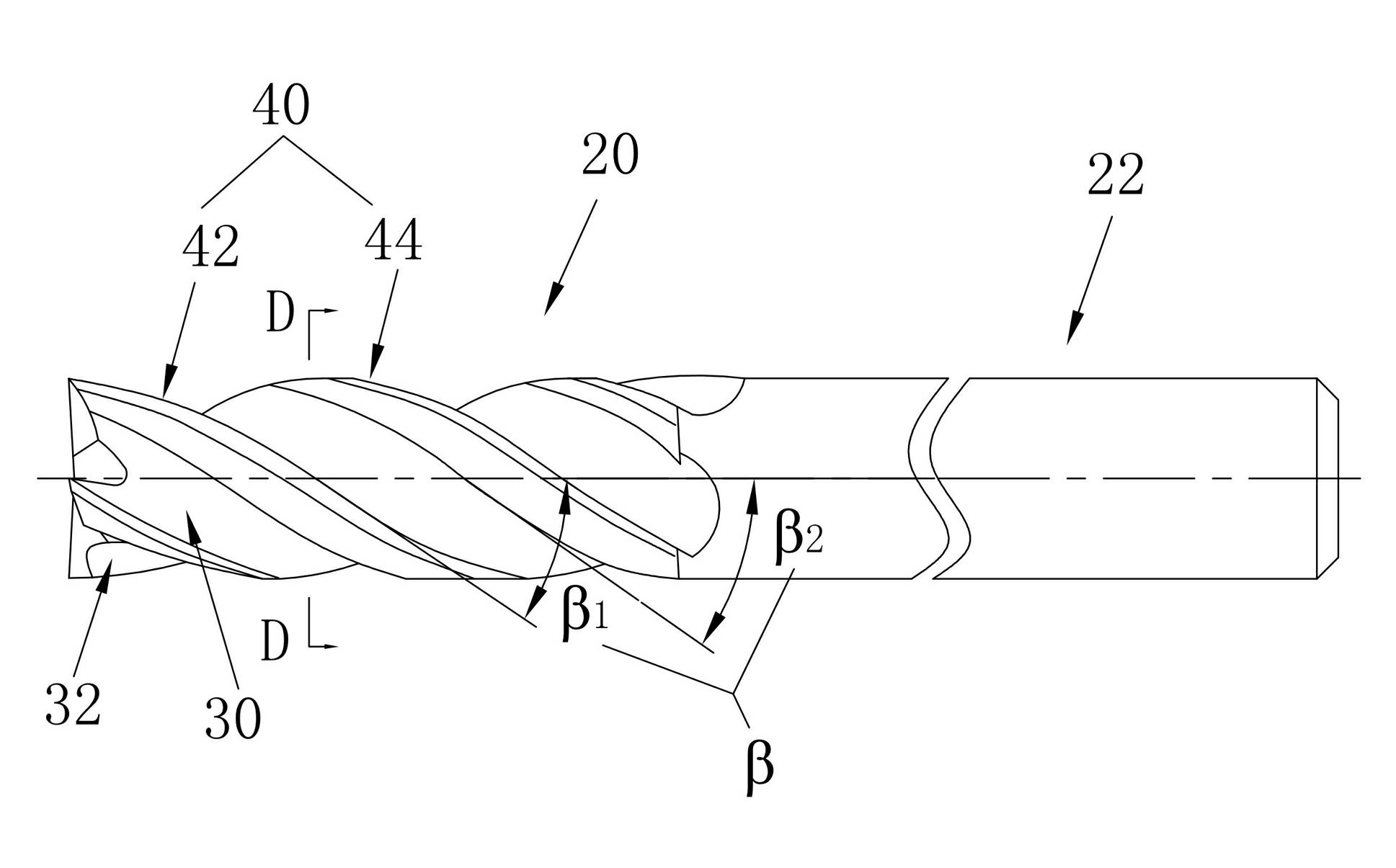
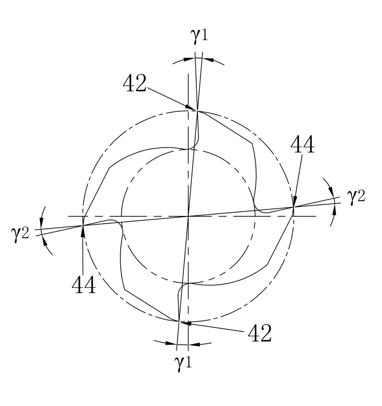
[0017] figure 1 and figure 2 It shows an embodiment of an end mill with equal actual rake angle and unequal helix angle of the present invention. The end mill includes a cutting part 20 and a shank part 22. Helically extending chip flute 30, the surface of chip flute 30 facing the cutting rotation direction is rake face 32, rake face 32 intersects with the outer peripheral surface of the cutting part to form peripheral cutting edge 40, at least one of the peripheral cutting edges 40 has a different helix angle β is different from the helix angle β of other peripheral cutting edges 40, and the radial rake angle γ of at least one peripheral cutting edge 40 is different from the radial rake angle γ of other peripheral cutting edges 40, the actual rake angle γ of each peripheral cutting edge 40 n equal, so that the tool can eliminate resonance to a large extent during high-efficiency milling and reduce the surface roughness of the workpiece to be machined; at the same time, the ...


PUM


Abstract

The invention discloses an end milling cutter with equal actual rake angles and unequal spiral angles. The end milling cutter comprises a cutting part and a handle part, wherein the whole cutting part is provided with a plurality of chip removal grooves which spirally extend from the bottom end to the handle part; the surfaces, which face the cutting rotation direction, of the chip removal grooves are front cutter surfaces; the front cutter surfaces are intersected with the peripheral surface of the cutting part to form peripheral blades; the spiral angle beta of at least one peripheral bladeis different from that of other peripheral blades; the radial rake angle gamma of at least one peripheral blade is different from that of other peripheral blades; and the actual rake angles gamma n of the peripheral blades are equal and accord with a formula: sine gamma n is equal to the sum of sine 2beta and cosine 2beta sine gamma. The end milling cutter with equal actual rake angles and unequal spiral angles can inhibit vibration during milling and improve milling stability and the collapse-resistant and wear-resistant comprehensive properties of the peripheral blades, so that the processing efficiency of the cutter is improved, and the service life of the cutter is prolonged.

Description

technical field [0001] The invention relates to the field of metal cutting, in particular to end mills with equal actual rake angles and unequal helix angles. Background technique [0002] Usually, the vibration generated by the end mill during cutting will cause the surface roughness to be machined to be reduced, and the tool will wear or chip prematurely, thereby limiting the life of the tool. Therefore, in order to suppress the vibration of the end mill, it has been proposed to make the helix angle of each helical tooth different, or to make the rake angle of each helical tooth or end tooth unequal. [0003] The U.S. patent document with the document number US20040120777A1 discloses such an end mill: the end mill body has a chip discharge flute, a cutting edge and a shank, and is formed on the outer peripheral side of a wall surface of a plurality of chip discharge flutes facing the rotation of the end mill Cutting edges, each cutting edge is not equally divided in the c...

Claims


Application Information

Patent Timeline
IPC IPC(8): B23C5/10
Inventor 许晋刘敏方曙璋
Owner ZHUZHOU CEMENTED CARBIDE CUTTING TOOLS CO LTD
Learn More