
Multifunctional ceramic slit antenna for distributing, loading and coupling in WIFI (Wireless Fidelity) compatible Big Dipper

A slot antenna, multi-functional technology, applied in the antenna grounding device, radiating element structure and other directions, to achieve the effect of small environmental factors, good radiation characteristics and small size

Inactive Publication Date: 2013-08-07
XIAMEN UNIV
View PDF2 Cites 0 Cited by
  • Summary
  • Abstract
  • Description
  • Claims
  • Application Information

AI Technical Summary

Problems solved by technology

[0014] Combining slot array, distributed loading coupling cavity control technology, and photonic bandgap structure, and applying it to the antenna design of satellite system has not been reported yet.

Method used


Image

  • Multifunctional ceramic slit antenna for distributing, loading and coupling in WIFI (Wireless Fidelity) compatible Big Dipper
  • Multifunctional ceramic slit antenna for distributing, loading and coupling in WIFI (Wireless Fidelity) compatible Big Dipper
  • Multifunctional ceramic slit antenna for distributing, loading and coupling in WIFI (Wireless Fidelity) compatible Big Dipper

Examples


Embodiment Construction

[0035] The present invention will be further described below in conjunction with embodiment and accompanying drawing.

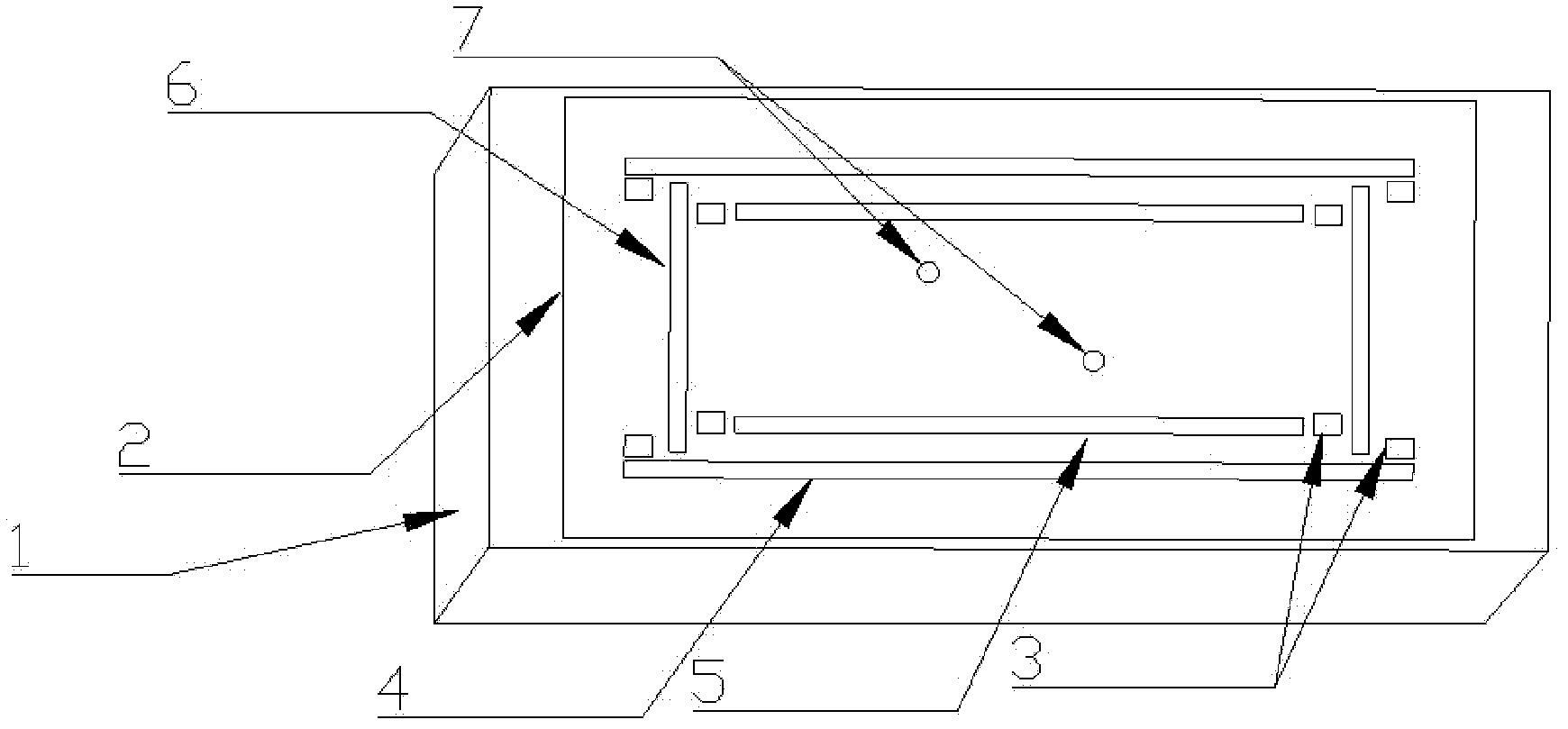
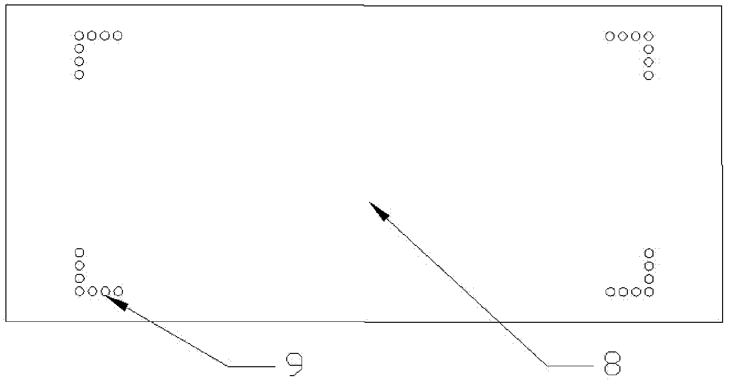
[0036] refer to figure 1 and figure 2 , the present invention is provided with double-sided copper-plated ceramic dielectric substrate 1, which is 50 mm long, 20 mm wide, and 2 mm high. Copper is coated on both sides of the ceramic dielectric substrate 1 , and the upper surface is a copper clad layer 2 with a pair of slot arrays 4 , a pair of slot arrays 5 , a pair of slot arrays 6 and a rectangular array hole loading coupling cavity 3 . Among them, the side length of the copper clad layer 2 is 42mm±0.01mm, the side width of the copper clad layer 2 is 19mm±0.01mm, the side length of the rectangular array hole loading coupling cavity hole 3 is 1.3mm±0.01mm, and the rectangular array hole loading The side width of the coupling cavity hole 3 is 1mm±0.01mm. In the copper clad layer 2 , the rectangular array hole loads the coupling cavity holes 3 and loads the...


PUM


Abstract

The invention provides a multifunctional ceramic slit antenna for distributing, loading and coupling in a WIFI (Wireless Fidelity) compatible Big Dipper, relating to a slit array ceramic antenna. The antenna is provided with a ceramic medium base plate and the upper surface of the base plate is provided with a three-slit rectangular radiation patch with a rectangular array hole loading and coupling cavity; the radiation patch is provided with three pairs of slit arrays; two pairs of the slit arrays are parallel to the long edge of the radiation patch and the third pair of the slit arrays are vertical to the long edge of the radiation patch; and the distance between the third pair of the slit arrays and the wide edge of the nearest patch is 1 / 8 of the length of the patch; the slit array radiation patch is provided with rectangular array holes; the rectangular array hole loading and coupling cavity is symmetrically distributed and a rectangular loading and coupling cavity array is composed of 4-10 rectangular small holes and is respectively loaded at two ends of the slit arrays; the lower surface of the base plate is in a circular hole array photonic band-gap structure and four groups of photonic band-gap arrays are loaded at four corners of a rectangular grounding plate; and in each group of the photonic band-gap array, an L band-gap array is formed by a plurality of rows of circular holes. The antenna provided by the invention has the advantages of low return loss, high gain, small interference and directed radiation and is compatible with WIF frequency ranges.

Description

technical field [0001] The invention relates to an improved slot array ceramic antenna, in particular to a ceramic antenna for a miniaturized distributed loading coupling cavity used in a Beidou satellite multi-frequency point compatible WIFI system. Background technique [0002] Since 2000, China has successfully launched 4 Beidou-1 navigation and positioning satellites and 7 Beidou-2 navigation and positioning satellites. As an indispensable part of the satellite communication system, the antenna directly determines the performance of the satellite communication system. my country's Beidou-2 satellite communication system works in the B1 and B3 frequency bands, the uplink (transmission frequency) L frequency band and the downlink (reception frequency) S frequency band. Dual-frequency or multi-frequency is usually used to compensate the delay caused by ionospheric propagation, which requires the antenna to have good working performance on each frequency. In addition, sinc...

Claims


Application Information

Patent Timeline
Patent Type & Authority Patents(China)
IPC IPC(8): H01Q1/38H01Q1/48
Inventor 游佰强王天石周志微周建华
Owner XIAMEN UNIV
Learn More