Insert, manufacturing method of insert, electromagnetic clutch with insert and manufacturing method of electromagnetic clutch
A clutch and insert technology, which is applied in the direction of magnetic drive clutches, clutches, non-mechanical drive clutches, etc., can solve the problems of electromagnetic fan clutch failure and adverse effects on users, and achieve simplified installation process, long service life and stable product performance. Effect
- Summary
- Abstract
- Description
- Claims
- Application Information
AI Technical Summary
Problems solved by technology
Method used
Image
Examples
Embodiment 1
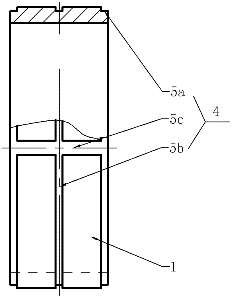
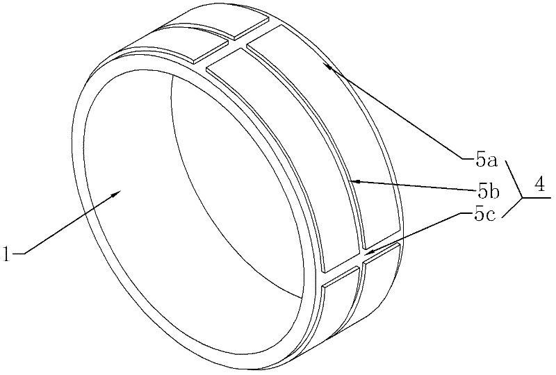
[0044] Such as figure 1 , figure 2 , Figure 10 As shown, an insert 1 of the present invention is used for an electromagnetic fan clutch including a bearing seat 2 and a bearing 3. The insert 1 is in the shape of a ring, and the left and right end faces of the insert 1 are connected with the outer surface. There is an annular right-angle groove 5a, an annular rectangular groove 5b is opened in the middle of the outer surface of the insert 1, and four axially distributed rectangular through grooves 5c are opened on the outer surface of the insert 1, and the rectangular through grooves 5c are evenly distributed in the insert 1 on the circumference of . The outer peripheral surface of insert 1 is in contact with bearing seat 2, and the inner surface of insert 1 is matched with bearing 3. The material of insert 1 is seamless steel pipe No. 20, and its expansion coefficient is 12 microns per meter per degree. The bearing steel The expansion coefficient is 12.5 microns per mete...
Embodiment 2
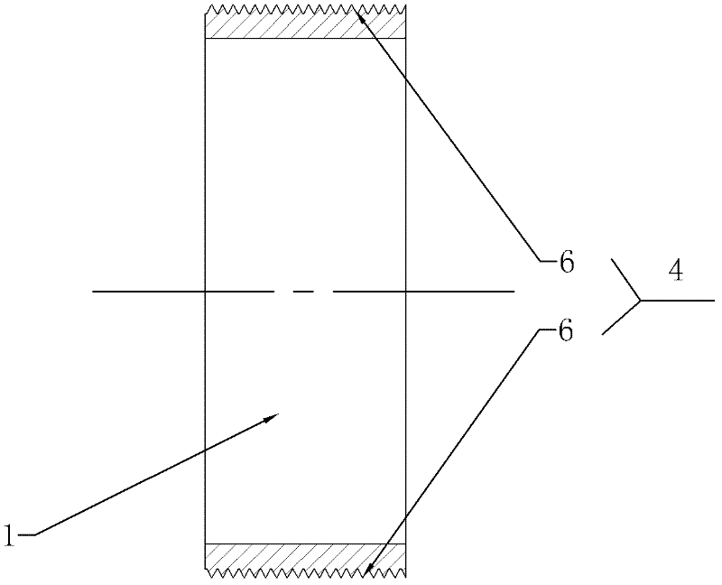
[0047] Such as image 3 , Figure 4 , Figure 12 As shown, an insert 1 of the present invention is used for an electromagnetic fan clutch including a bearing seat 2 and a bearing 3 . The insert 1 is in the shape of a ring, and a thread groove 6 is processed on the outer surface of the insert 1 . The outer peripheral surface of insert 1 is in contact with bearing seat 2, and the inner surface of insert 1 is matched with bearing 3. The material of insert 1 is seamless steel pipe No. 20, and its expansion coefficient is 12 microns per meter per degree. The bearing steel The expansion coefficient is 12.5 microns per meter per degree, the expansion coefficient of aluminum is 24 microns per meter per degree, and the expansion coefficient of insert 1 is close to that of bearing 3. The material of the above-mentioned insert 1 can also be a seamless steel pipe with an expansion coefficient of 11.25 microns per meter per degree, or a seamless steel pipe with an expansion coefficient o...
Embodiment 3
[0050] Such as Figure 5 , Figure 6 , Figure 13 As shown, an insert 1 of the present invention is used for an electromagnetic fan clutch including a bearing seat 2 and a bearing 3. The insert 1 is in the shape of a ring, and four through holes 7 are opened on the outer surface of the insert 1. The through holes 7 are formed after the groove 4 passes through the ring body of the insert 1. The four through holes 7 are evenly distributed along the circumference of the insert 1, and the axes of the two opposite through holes 7 coincide, and the axes of the two through holes 7 are adjacent to each other. parallel. The outer peripheral surface of the insert 1 is in contact with the bearing seat 2, and the inner surface of the insert 1 is matched with the bearing 3. The material of the insert 1 is iron-based powder metallurgy material, and its expansion coefficient is 12.25 microns per meter per degree, and the bearing steel The expansion coefficient is 12.5 microns per meter pe...
PUM
 Abstract
Description
Claims
Application Information
 - R&D
- Intellectual Property
- Life Sciences
- Materials
- Tech Scout
- Unparalleled Data Quality
- Higher Quality Content
- 60% Fewer Hallucinations
Browse by: Latest US Patents, China's latest patents, Technical Efficacy Thesaurus, Application Domain, Technology Topic, Popular Technical Reports.
© 2025 PatSnap. All rights reserved.Legal|Privacy policy|Modern Slavery Act Transparency Statement|Sitemap|About US| Contact US: help@patsnap.com


