
Method for drawing grin lens fiber

A lens fiber and prefabricated technology, applied in glass fiber drawing devices, lenses, glass fiber products, etc., can solve the problems of loss, disconnection, long time, etc., and achieve the effect of reducing waste

Inactive Publication Date: 2012-02-29
TOYO SEIKAN GRP HLDG LTD
View PDF3 Cites 0 Cited by
  • Summary
  • Abstract
  • Description
  • Claims
  • Application Information

AI Technical Summary

Problems solved by technology

[0008] In the past, the method of drawing GRIN lens preforms was to soften and extend the part 12-18mm away from the lower end of the preform, so the part of the preform should be at least 15-21mm (accounting for about 1 / 3-1 / 2 of the length of the preform) It cannot be drawn into fibers, which will cause waste
GRIN lens preforms are expensive and valuable, such waste is a great loss in terms of cost
[0009] In addition, the weight of the preform with a length of 12 to 18 mm is about 0.5 to 0.8 g, so the softened portion descends very slowly, and it takes a very long time until the start of winding
As a means of shortening the time until the start of coiling, a method of increasing the heating temperature and reducing the viscosity of the preform can be considered. However, the quartz glass used for the GRIN lens contains dopants (titanium and tantalum, etc., which impart a gradient refractive index) , so the viscosity changes with the temperature change is relatively large, it is likely that the melted stretched part becomes too thin during the heating process so that the wire cannot be wound, or the melted stretched part is disconnected, so that the waste of the preform will be more
[0010] In addition, the techniques shown in the above-mentioned patent documents 2 and 3 are the techniques used when the ordinary optical fiber starts to be drawn, and cannot play a role at all when drawing the GRIN lens preform that is much smaller than the optical fiber preform.

Method used


Image

  • Method for drawing grin lens fiber
  • Method for drawing grin lens fiber
  • Method for drawing grin lens fiber

Examples


Embodiment

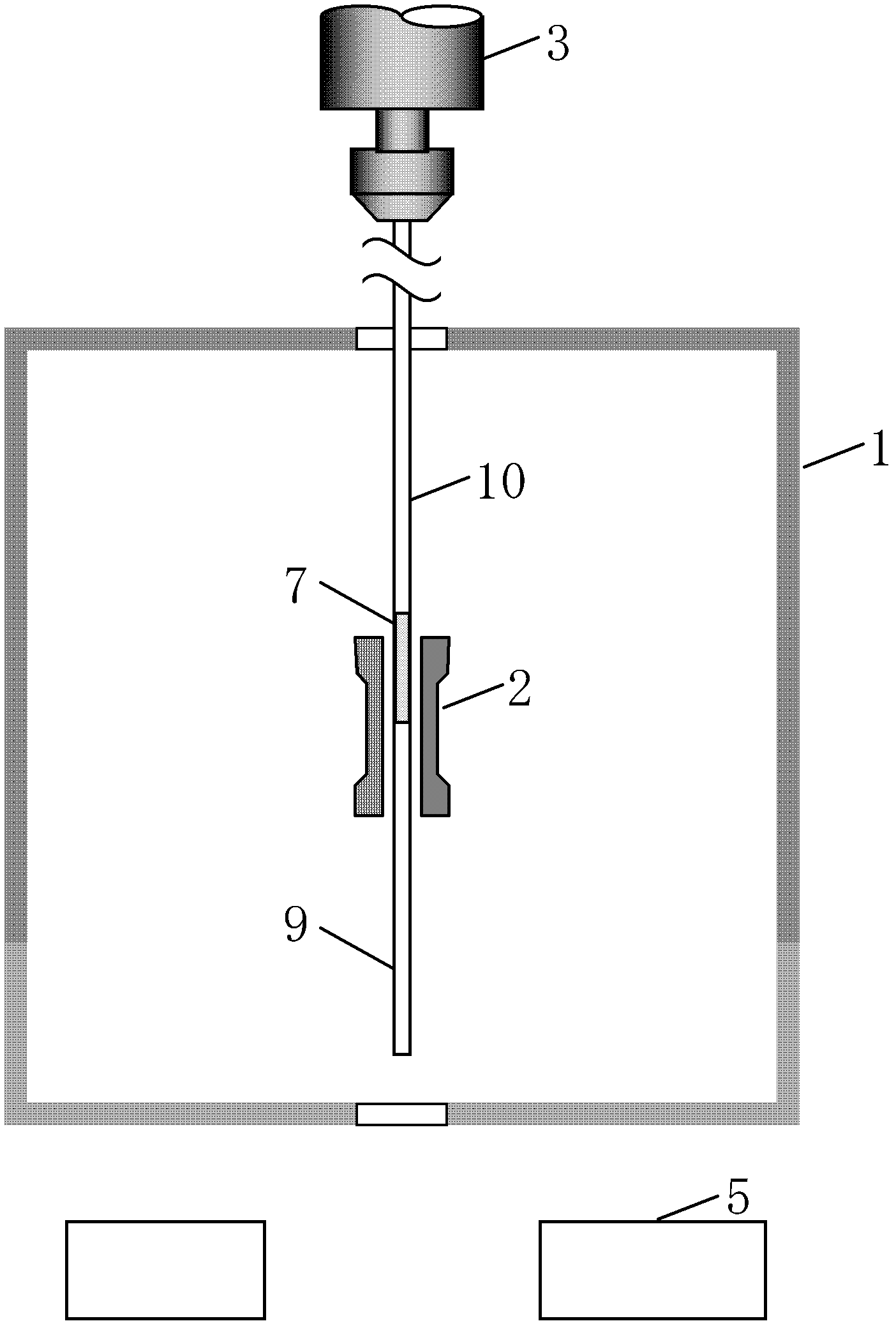
[0042] figure 1 with 4 Shown is the GRIN lens fiber drawing device. The wire drawing device has a heating furnace 1, a heater 2, a lifting device 3, a reel 4, a wire diameter measuring instrument 5 and an automatic control device 6.

[0043] The heating furnace 1 is an ultra-high temperature vertical tubular furnace capable of heating up to 2100°C.

[0044] The reel 4 has a transverse movement mechanism to prevent the fibers from overlapping. In this embodiment, the drawn GRIN lens fiber is directly wound on the reel 4, and the drawing speed is controlled by controlling the reel rotation speed. You can also set a guide wheel in front of the reel to control the drawing speed by controlling the speed of the guide wheel.

[0045] A lifting device 3 is provided above the heating furnace 1 to hold and lift the preform 7.

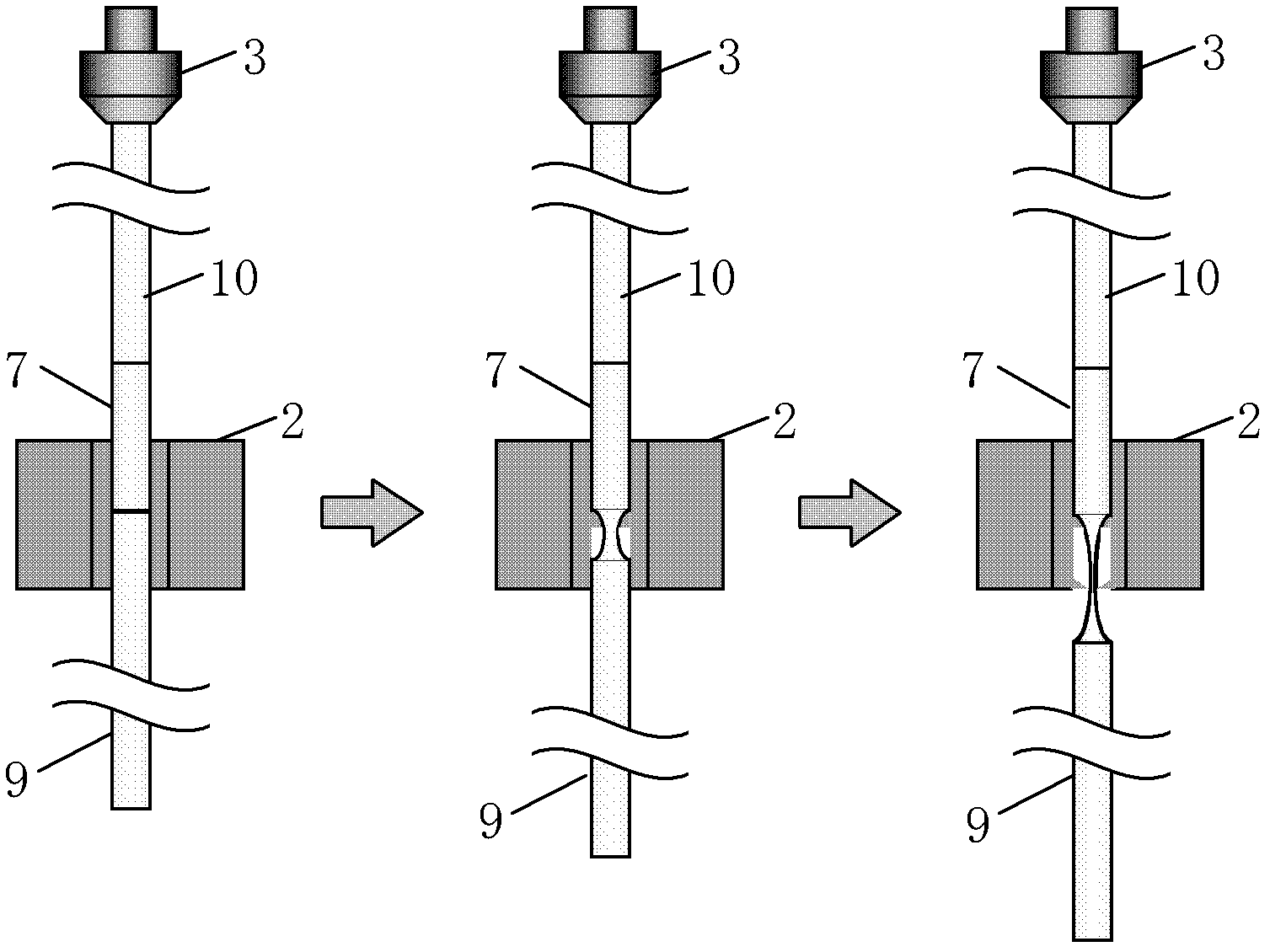
[0046] A quartz rod 10 is welded to one end (upper end) of the preform 7, and a weight 9 is welded to the other end (lower end). The quartz rod 10 is a rod-shaped ma...


PUM


Abstract

Disclosed is a method for drawing a GRIN lens fiber wherein waste of preform is reduced when drawing of a GRIN lens from a preform is started, and the time from start of elongation to start of winding of a preform is shortened. Since a preform having a weight fusion-bonded to the lower end is set in a heating furnace and drawing of a preform is started by heating the fusion-bonded portion of the preform and the weight, waste of the preform can be reduced. Since elongation speed of the preform is increased by the weight, the time from start of the elongation to start of the winding of the preform can be shortened.

Description

Technical field [0001] The invention relates to a method for drawing a GRIN lens fiber from a preform in the drawing method of a GRIN lens fiber, and particularly relates to a method for shortening the time when starting the drawing and reducing the waste of the preform. Background technique [0002] The so-called GRIN lens fiber refers to a cylindrical gradient index lens (GRaded INdex lens), which functions as a lens by changing the direction of light by forming a gradient index inside the glass. Generally, a lens cut to approximately 1 mm is fused to the top of the optical fiber and used for various applications of optical systems for optical communications. In recent years, the demand for high NA (number of openings) GRIN lenses has increased. As disclosed in the following Patent Document 1, etc., preforms of such GRIN lenses are manufactured by a sol-gel method. The smallest preform 7 made by the sol-gel method has a diameter of about 5 mm and a length of about 30-50 mm, an...

Claims


Application Information

Patent Timeline
Patent Type & Authority Applications(China)
IPC IPC(8): C03B37/02G02B3/00G02B6/028
CPCC03B37/02772C03B2203/26C03B2205/47G02B3/0087G02B6/028C03B37/02G02B3/00
Inventor 福田敏明
Owner TOYO SEIKAN GRP HLDG LTD
Learn More