
System and method for wireless measuring illumination

A technology for illuminance measurement and wireless measurement, which is applied in wireless communication, signal transmission system, and photometry using electrical radiation detectors. Simple, low power, low cost effect

Inactive Publication Date: 2012-02-15
厦门市产品质量监督检验院
View PDF7 Cites 13 Cited by
  • Summary
  • Abstract
  • Description
  • Claims
  • Application Information

AI Technical Summary

Problems solved by technology

[0004] The purpose of the present invention is to provide a wireless illuminance measurement system and its method, which solves the problems of high cost, poor accuracy, low efficiency, and complicated data recording in the prior art for road illuminance measurement

Method used


Image

  • System and method for wireless measuring illumination
  • System and method for wireless measuring illumination
  • System and method for wireless measuring illumination

Examples


Embodiment Construction

[0039] The above solution will be further described below in conjunction with specific embodiments. It should be understood that these examples are used to illustrate the present invention and not to limit the scope of the present invention. The implementation conditions used in the examples can be further adjusted according to the conditions of specific manufacturers, and the implementation conditions not indicated are usually the conditions in routine experiments.

[0040] Embodiment Wireless illuminance measurement system in a certain area

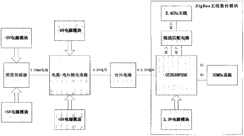
[0041] Such as figure 1 , the wireless illuminance measurement system of this embodiment adopts such as figure 1 The network communication system structure shown includes: several ZigBee illumination measurement terminals, ZigBee-GPRS gateway, GPRS server and several clients. The ZigBee illuminance measurement terminal utilizes an illuminance sensor to collect road illuminance, and then utilizes ZigBee technology to wirelessly send the...


PUM


Abstract

The invention discloses a system and a method for wireless measuring illumination. The wireless measurement system is characterized by comprising a plurality of Zigbee illumination measurement terminals, a Zigbee-general packet radio service (Zigbee-GPRS) gateway, a GPRS server and a plurality of clients. The Zigbee illumination measurement terminals acquire illumination by utilizing an illumination sensor and then wirelessly transmit illumination data to a remote Zigbee-GPRS gateway by utilizing a Zigbee technology; and the gateway remotely and wirelessly transmits the illumination data to the GPRS server by utilizing a GPRS technology, so that high performance remote transmission of the illumination data is realized. The plurality of clients can query the illumination data acquired by all Zigbee illumination measurement terminals through the Internet network.

Description

technical field [0001] The invention belongs to the technical field of illuminance measurement and wireless communication, in particular to a system and method for collecting and wirelessly transmitting illuminance by using sensor technology, ZigBee and GPRS wireless communication technology. Background technique [0002] Traditional fieldbuses are also used in road lighting control, but most of them have complex communication interface protocols and need to lay special cables, which have problems such as high cost and inconvenient maintenance; narrowband power line carriers directly use power lines for data communication, saving The installation of special cables is removed, the construction is flexible, and it has the characteristics of high cost performance, convenient upgrade, and simple maintenance. However, it has the disadvantages of large power line interference and slow transmission rate, and the reliability of large-scale applications has yet to be verified. With t...

Claims


Application Information

Patent Timeline
IPC IPC(8): H04W84/18G08C17/02G01J1/42
Inventor 田力军庄鹏
Owner 厦门市产品质量监督检验院
Learn More