
Strip line radio-frequency unit and packaging structure thereof

A technology of radio frequency components and packaging structure, which is applied in the direction of electrical components, connecting devices, waveguide devices, etc., can solve the problems that radio frequency components are difficult to take advantage of, there are many influencing factors of electrical indicators, and passive intermodulation indicators are out of control, etc., so as to achieve easy assembly High efficiency, low passive intermodulation products, simple and compact structure

Inactive Publication Date: 2012-02-15
COMBA TELECOM SYST CHINA LTD
View PDF4 Cites 10 Cited by
  • Summary
  • Abstract
  • Description
  • Claims
  • Application Information

AI Technical Summary

Problems solved by technology

[0004] First of all, multiple screws are used to fasten the cavity and the cover plate in the form of "line contact", which involves many parts, high cost and long assembly time;
[0005] Secondly, there are many factors affecting the electrical index, especially the intermodulation index is limited by the fastening characteristics of multiple screws between the cover plate and the cavity. As long as one screw is loose, the passive intermodulation index will be out of control;
[0006] Therefore, due to the price and electrical indicators, the current RF components of this structure are difficult to gain an advantage in the fierce competition

Method used


Image

  • Strip line radio-frequency unit and packaging structure thereof
  • Strip line radio-frequency unit and packaging structure thereof
  • Strip line radio-frequency unit and packaging structure thereof

Examples


Embodiment Construction

[0022] Below in conjunction with accompanying drawing and embodiment the present invention will be further described:

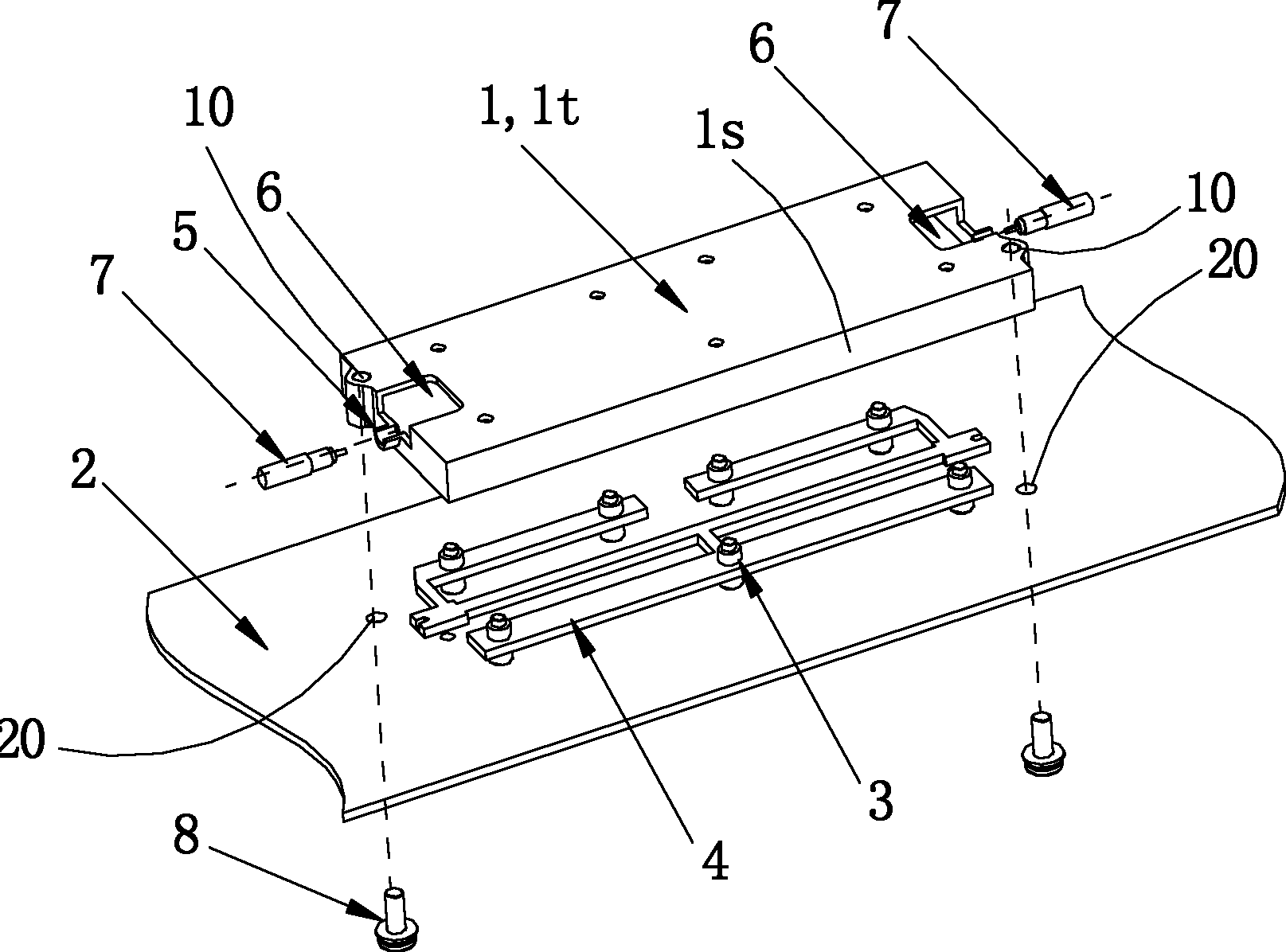
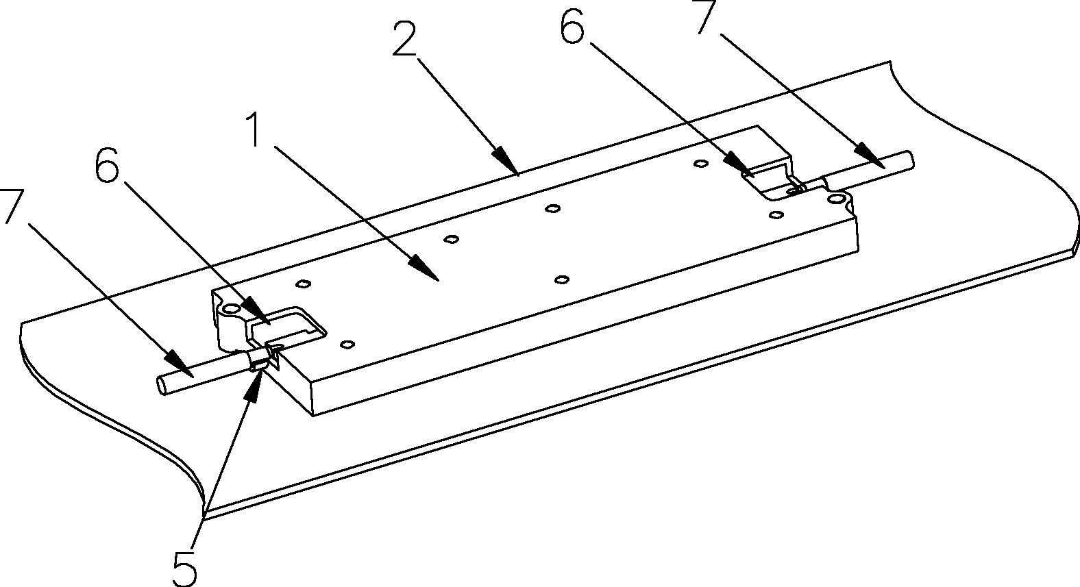
[0023] see figure 1 and figure 2 , in a preferred embodiment of the stripline radio frequency component packaging structure of the present invention, the package structure includes a cap 1 , a reflector 2 , a dielectric support 3 and a stripline radio frequency component 4 .

[0024] The reflector 2 is made of metal material. The reflector 2 is located at the bottom of the stripline radio frequency component 4, and it supports the stripline radio frequency component 4 through some dielectric support members 3 passing through the reflector 2, and the reflector 2 is also preset for matching with the cap 1 Other screw holes 20 for screw locks. The reflector 2 has a certain thickness and strength, and its specific thickness and material type can be flexibly changed. Structurally, the reflector 2 plays the role of fixing the cap 1 and the stripline radio frequ...


PUM


Abstract

The invention mainly discloses a packaging structure of a strip line radio-frequency unit, comprising a reflection board and a cover cap, wherein the cover cap and the reflection board are installed stably and fixedly in the form of at least two point contact; the cover cap forms a groove-shaped cavity which is used for accommodating the strip line radio-frequency unit which is fixedly installed on the reflection board, and the cover cap is provided with at least two connection ports which are used for connecting external cables with the cover cap and connecting the external cables with the strip line radio-frequency unit electrically after the external cable passes through the cover cap. The packaging structure is used for packaging power division networks / high-pass networks / low-pass networks / band-pass networks / duplexing networks / combiner networks to form a strip line power divider / a strip line high-pass filter / a strip line low-pass filter / a strip line band-pass filter / a strip line duplexer / a strip line combiner and other strip line radio-frequency units correspondingly. Due to the adoption of a point contact installation mode for the cover cap and the reflection board in the packaging structure, the formed device has preferable passive intermodulation indexes; and the packaging structure is simple in structure, easy to assemble, saved in materials, and beneficial to large-scale batch production.

Description

【Technical field】 [0001] The invention relates to a stripline radio frequency component and its packaging structure, especially suitable for various stripline radio frequency components required by mobile communication systems. 【Background technique】 [0002] With the rapid development of wireless communication technology, the competition among communication equipment manufacturing industries has become very fierce. The eternal theme of competition is: high performance indicators and low cost. [0003] At present, the commonly used RF component packaging structure designed based on the working principle of RF stripline generally adopts the form of a box body formed by fastening the cavity and the cover plate with multiple screws. This installation structure has the following disadvantages: [0004] First of all, multiple screws are used to fasten the cavity and the cover plate in the form of "line contact", which involves many parts, high cost and long assembly time; [000...

Claims


Application Information

Patent Timeline
Patent Type & Authority Applications(China)
IPC IPC(8): H01P5/12H01P1/203H01P1/213
Inventor 刘培涛卢吉水孙善球
Owner COMBA TELECOM SYST CHINA LTD
Learn More