
Superlens based on artificial electromagnetic structure in nuclear magnetic resonance imaging

A nuclear magnetic resonance imaging and artificial electromagnetic technology, which is used in medical science, sensors, diagnostic recording/measurement, etc., can solve the limitation of the working frequency and working bandwidth of the electromagnetic superlens, the difficulty of designing the electromagnetic superlens, and the difficulty of making hardware equipment such as detection coils. and other problems, to achieve the effect of structural scalability, high signal-to-noise ratio, and high spatial resolution

Inactive Publication Date: 2012-02-15
ZHEJIANG UNIV
View PDF2 Cites 8 Cited by
  • Summary
  • Abstract
  • Description
  • Claims
  • Application Information

AI Technical Summary

Problems solved by technology

However, as the magnetic field strength increases, the radio frequency electromagnetic waves will cause greater damage to the human body. Therefore, European and American countries have strict restrictions on the use of magnetic field strength; at the same time, as the field strength increases, detection coils and other hardware equipment There is also this great difficulty in the production of
On the other hand, the design of electromagnetic metalens is also one of the difficulties in all these works
Theoretical analysis has shown that in order to achieve the above "perfect imaging", the structural parameters must strictly meet the permittivity of -1 or the magnetic permeability of -1, thus strictly limiting the operating frequency and operating bandwidth of the electromagnetic metalens

Method used


Image

  • Superlens based on artificial electromagnetic structure in nuclear magnetic resonance imaging
  • Superlens based on artificial electromagnetic structure in nuclear magnetic resonance imaging
  • Superlens based on artificial electromagnetic structure in nuclear magnetic resonance imaging

Examples


Embodiment Construction

[0018] The present invention will be further described below in conjunction with accompanying drawing.

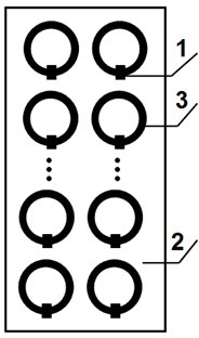
[0019] The invention designs a curved annular artificial electromagnetic hyperlens based on an LC loop resonance unit, and utilizes its novel electromagnetic properties to enhance signal excitation response and detection of surface coils in nuclear magnetic resonance imaging. Under the same equipment conditions, the electromagnetic metalens can realize the focusing of the excitation coil and the super-resolution imaging of the detection coil in the MRI system, so it can realize depth and fixed-point (limited area size) detection, and effectively improve the signal-to-noise ratio.

[0020] Such as image 3 As shown, a metalens based on artificial electromagnetic structure in nuclear magnetic resonance imaging includes an inner fixed ring, an outer fixed ring and a plurality of resonance units 4, and the resonance unit 4 is vertically arranged between the inner fixed ring and...


PUM


Abstract

The invention relates to a superlens based on an artificial electromagnetic structure. Traditional equipment restricts the operating frequency and operating bandwidth of electromagnetic superlenses. The superlens comprises an inner fixed ring, an outer fixed ring and a plurality of resonance units, wherein the resonance units are vertically arranged between the inner fixed ring and the outer fixed ring; the inner and outer fixed rings are concentrically arranged; the plurality of resonance units are uniformly distributed with the circle center as the center; each resonance unit comprises an elongated FR-4 substrate, a plurality of LC loop resonance units and a plurality of nonmagnetic load capacitors; the LC loop resonance units are transversely and longitudinally distributed on the elongated FR-4 substrate uniformly; each LC loop resonance unit corresponds to a nonmagnetic load capacitor; and the nonmagnetic load capacitors are mounted at the openings of the LC loop resonance units. The superlens has the following beneficial effects: the manufacturing process is simple and the structure is extensile; and high spatial resolution and signal to noise ratio can be realized by introducing the resonance unit structures to the conventional nuclear magnetic resonance imaging equipment.

Description

technical field [0001] The invention belongs to the field of nuclear magnetic resonance medical imaging, and relates to a hyperlens based on an artificial electromagnetic structure. Background technique [0002] MRI is a biological magnetic spin imaging technology. It uses the characteristics of the spin motion of hydrogen nuclei in the human body. In an external magnetic field, a signal is generated after being excited by a radio frequency pulse (Radio frequency). It is detected by a detector and input into a computer. Image processing technology displays images on the screen. According to the different attenuation of the energy released by human tissue in different structural environments inside the material, the position and type of the atomic nucleus that constitutes the object can be known through the detection of the emitted electromagnetic waves by an external gradient magnetic field, and the interior of the object can be drawn accordingly structure image. As a new ...

Claims


Application Information

Patent Timeline
Patent Type & Authority Applications(China)
IPC IPC(8): A61B5/055
Inventor 谢易宏何赛灵金毅刘强
Owner ZHEJIANG UNIV
Learn More