
High-torque continuously variable transmission

A technology of continuously variable transmission and continuously variable transmission unit, which is applied to belts/chains/gears, mechanical equipment, transmission devices, etc., and can solve problems such as the inability to meet the demand for high torque, and meet the demand for high power and high torque the effect of the demand

Inactive Publication Date: 2012-02-01
SICHUAN UNIV
View PDF2 Cites 4 Cited by
  • Summary
  • Abstract
  • Description
  • Claims
  • Application Information

AI Technical Summary

Problems solved by technology

Due to the limitation of the shear limit of traction oil and the limit of bending strength of moving component materials, the torque transmitted only by the traction semi-torusal continuously variable transmission cannot meet the demand for large torque during construction machinery operations

Method used


Image

  • High-torque continuously variable transmission
  • High-torque continuously variable transmission
  • High-torque continuously variable transmission

Examples


Embodiment Construction

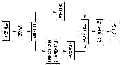
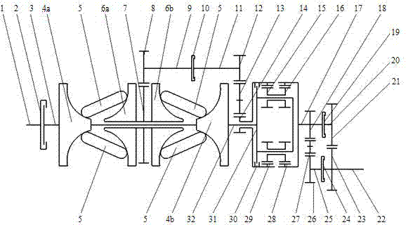
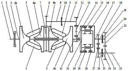
[0010] see figure 1 , 2 , High-torque continuously variable transmission, including traction-driven double-cavity semi-torusal continuously variable transmission unit, fixed-axis gear train, double-row differential gear train and output reversing mechanism. Among them, the double-cavity semi-torus type continuously variable transmission unit includes 2 input cones (4a, 4b), 2 output cones (6a, 6b) and 4 power transmission rollers (5), the input cone (4a ) and the output cone (6a) form a semi-annular cavity, in which two power transmission rollers (5) are symmetrically distributed; similarly, the input cone (4b) and the output cone (6b) A semi-annular cavity is formed, and two power transmission rollers (5) are symmetrically distributed in the cavity; the fixed-axis gear train consists of the first gear (7), the second gear (8), the first countershaft (9 ), the second clutch (10), the second countershaft (11), the third gear (12), the fourth gear (13), and the fifth gear (14)...


PUM


Abstract

The invention relates to a high-torque continuously variable transmission for transferring high torque. The continuously variable transmission consists of a double-cavity half-toroid continuously variable unit, an ordinary gear train, a double-row differential train and a reversing mechanism which are in traction drive, wherein input power is transmitted in two paths of which one path is transferred to a planet carrier of the double-row differential train through a main shaft, and the other path is transferred to a fifth gear of the double-row differential train through the double-cavity half-toroid continuously variable unit and the ordinary gear train; the two parts of power is output through a second inner gear after being converged at the double-row differential train; an odd number of external engagements of gears of the ordinary gear train are designed, so that the implementation of power split in a closed system is guaranteed; and high-torque output of the continuously variable transmission is guaranteed by the rational selection of the number of the gears of the double-row differential train. In order to meet the requirements of advancing and retreating, during the operation of engineering machinery, the device is provided with the reversing mechanism at the output end.

Description

technical field [0001] The invention relates to a speed change mechanism in a drive train, specifically a continuously variable transmission. Background technique [0002] The metal belt continuously variable transmission that has been installed in the car is limited by the friction coefficient between the metals and the belt tensile capacity, and can only transmit at most The torque is suitable for medium and small displacement cars. Compared with the metal belt CVT, the traction semi-torusal CVT transmits motion and power by means of the traction oil located in the contact area of ​​the input, output cone and power transmission roller, which greatly improves the friction conditions between the contact surfaces , which improves the carrying capacity of the half-torus continuously variable transmission, and is suitable for large-displacement cars. Due to the limitation of the shear limit of traction oil and the limit of bending strength of moving component materials, the...

Claims


Application Information

Patent Timeline
Patent Type & Authority Applications(China)
IPC IPC(8): F16H37/02
Inventor 张庆功李华姚进
Owner SICHUAN UNIV
Learn More