Eureka AIR delivers breakthrough ideas for toughest innovation challenges, trusted by R&D personnel around the world.

Miniature microphone testing device

A microphone test and microphone technology, applied in the direction of sensors, electrical components, etc., can solve problems such as error-prone, low efficiency, and difficult performance parameter testing, so as to improve efficiency and accuracy, increase contact probability, and realize the effect of automation

Inactive Publication Date: 2012-01-25
GOERTEK INC
View PDF4 Cites 11 Cited by
  • Summary
  • Abstract
  • Description
  • Claims
  • Application Information

AI Technical Summary

Problems solved by technology

However, as we all know, the small size of the miniature microphone product determines that it is difficult to electrically connect the test probe to the pad of the test microphone by manual operation. In this case, it is very difficult to test the performance parameters of the miniature microphone product. Inefficient and very error-prone, it is impossible to accurately test the performance parameters of microphone products
[0004] Moreover, the currently more commonly used miniature microphone products are generally cylindrical miniature microphone products. The pads of the miniature microphones used to connect to external circuits are generally provided with two pads, a positive terminal and a negative terminal. The miniature microphone products are very easy to slide, resulting in The angle of the two pads of the positive terminal and the negative terminal is easy to change
If automated testing methods are used to test the miniature microphone, since the position of the pad of the miniature microphone product is uncertain, it is easy to cause the test probe of the test equipment to not accurately correspond to the pad of the correct polarity of the miniature microphone, and it is difficult to realize the automation of the test

Method used


Image

  • Miniature microphone testing device
  • Miniature microphone testing device
  • Miniature microphone testing device

Examples


Embodiment Construction

[0022] The present invention will be further described in detail below in conjunction with the accompanying drawings and specific embodiments.

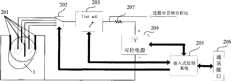
[0023] figure 2 It is a structural schematic diagram showing an embodiment of the microphone testing device of the present invention. like figure 2 As shown, the miniature microphone testing device provided by the present invention includes a test probe set 201, a channel selection switch 202, a current detection device 203, a controllable power supply 204, an embedded control unit 205 and a communication interface 206, wherein the test probe set includes At least one peripheral probe and a plurality of inner ring probes.

[0024] In the present invention, the embedded control unit 205 is the control core of the whole miniature microphone testing device. Before the test, the peripheral probes and the inner ring probes of the test probe set 201 are respectively in contact with the shell of the miniature microphone 1 and the circui...


PUM


Abstract

The invention provides a miniature microphone testing device, which comprises a testing probe group, a power supply, a channel selection switch, a current detection device and an embedded control unit, wherein the testing probe group comprises at least one peripheral probe used for being connected with a shell of a miniature microphone and a plurality of inner ring probes used for being connected with a circuit board of the miniature microphone, and the channel selection switch is connected with the inner ring probes and is used for being communicated with one of the inner ring probes according to a control instruction of the embedded control unit to form a testing circuit; the current detection device is used for detecting the current of the testing circuit; and the embedded control unit is used for setting bias voltage, controlling the channel selection switch to be communicated with the testing circuit and analyzing the current of the testing circuit. With the device, the miniature microphone can be effectively tested automatically, and the testing efficiency and accuracy can be improved.

Description

technical field [0001] The invention relates to the technical field of testing microelectronic components, in particular to a miniature microphone testing device. Background technique [0002] In recent years, miniature microphone products have gradually been widely used in electronic products. Generally speaking, miniature microphone products can be assembled through automated production with relatively high efficiency. For example, the Chinese patent application number 200920027762.5 discloses a miniature microphone that is convenient for automatic production. However, due to the small size of the miniature microphone, it is generally in the volume of tens or even tens of cubic millimeters, while the traditional miniature microphone test is generally It is all manual testing, so this volume makes product testing very difficult. [0003] figure 1 It is a schematic diagram of an existing device for manually testing analog microphones, such as figure 1 As shown, before usi...

Claims


Application Information

Patent Timeline
IPC IPC(8): H04R31/00
Inventor 王维奎邱东
Owner GOERTEK INC
Why Eureka
Eureka Blog
Learn More