
Water tank wire drawing machine

A water tank wire drawing machine and wire drawing technology, which is applied in the field of metal product production, can solve the problems of long assembly line, frequent shutdown, and large floor space, and achieve uniform and stable drawing speed, ensure the quality of finished products, and occupy a small floor area.

Active Publication Date: 2012-01-25
WUXI CHANGXIN TECH
View PDF7 Cites 16 Cited by
  • Summary
  • Abstract
  • Description
  • Claims
  • Application Information

AI Technical Summary

Problems solved by technology

[0003] The existing dry drawing machine has a large frictional resistance, short service life of the wire drawing die, serious work hardening, low allowable total compression rate, small variation range of partial compression rate, and low strength of the final product steel wire
During the drawing process, brittle fractures often occur, there are many steel wire joints, frequent shutdowns, and low production efficiency
Moreover, the steel wire drawn by the dry drawing machine needs to undergo intermediate heat treatment before it can be further drawn. There are many processes, large material consumption, and high production costs.
[0004] The existing water tank wire drawing machine is relatively large in size, occupies a large area, and has a long assembly line. In the actual production process, it is easily affected by various factors in the production environment. The upper winding is uneven, the arrangement is not neat, and there is a problem of crimping, which leads to broken wires in the subsequent use of the product

Method used


Image

  • Water tank wire drawing machine
  • Water tank wire drawing machine
  • Water tank wire drawing machine

Examples


Embodiment Construction

[0030] The present invention will be further described below in conjunction with specific drawings and embodiments.

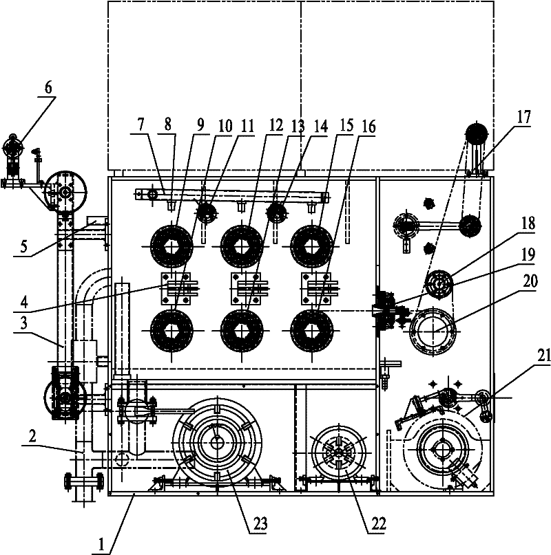
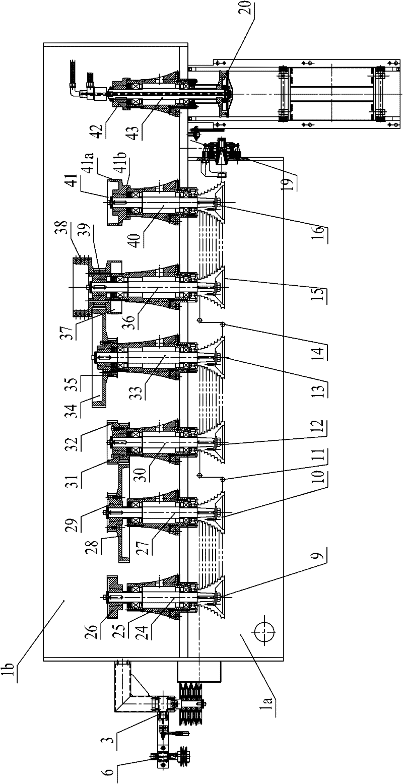
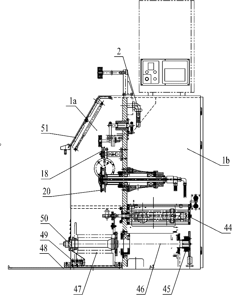
[0031] The wire drawing machine is mainly composed of a wire drawing host and a wire take-up device 21 .

[0032] Such as Figure 1~Figure 3 As shown, the wire drawing host includes a box body 1, and a tension mechanism 3 is installed on the left side wall of the box body 1, and the tension mechanism 3 is used to maintain a stable tension force on the steel wire before starting wire drawing. A guide roller 6 for introducing steel wires is installed; a wire feeding box 5 is installed on the left side wall of the casing 1 , and the steel wire after the tension mechanism 3 adjusts tension passes through the wire feeding box 5 into the casing 1 .

[0033] The structure of the tension mechanism 3 is specifically as in 5.1~ Figure 5.4 As shown, it is mainly made up of support 3.9, column 3.8, lower fixed plate 3.7, lower wheel axle 3.2, upper fixed plate 3.10 and ...


PUM


Abstract

The invention relates to a water tank wire drawing machine. The water tank wire drawing machine comprises a wire drawing main machine and a take-up device, and is characterized in that the wire drawing main machine comprises a box body, wherein a tension mechanism is mounted on the left side wall of the box body; a wire inlet box is mounted on the left side wall of the box body, and a steel wire penetrates into the box body via the wire inlet box; a main motor is mounted at the lower part of the box body, the box body is divided into two parts, namely a transmission box and a water tank, a transmission device is mounted in the transmission box, and the transmission device is driven by relying on the main motor; a wire outlet die box is mounted on the right side wall of the water tank; anda wire guide shaft and a traction and orientation mechanism are mounted on the box body, the back end of the wire guide shaft extends into the transmission box and is linked with the transmission device, a wire guide wheel is mounted at the front end of the wire guide shaft, and the steel wire which penetrates out of the wire outlet die box is firstly wound on the wire guide wheel for one circle,then wound on the traction and orientation mechanism for multiple circles and further led to the take-up device. The water tank wire drawing machine is ingenious, compact and reasonable in structure,small in floor area, and uniform and stable in drawing speed, and can ensure the quality of a steel wire finished product.

Description

technical field [0001] The invention belongs to the technical field of metal product production, and relates to wire drawing equipment, in particular to a water tank wire drawing machine. Background technique [0002] With the development of the metal products industry, high speed, high efficiency, low cost and strong process adaptability have become the pursuit goals of production enterprises. Wire drawing machine is a kind of mechanical equipment widely used in machinery manufacturing, metal processing, petrochemical industry, wire and cable and other industries. It is used to draw wire or rod to make the diameter, roundness, The internal metallographic structure, surface finish and straightening degree all meet the raw material processing requirements for the production of standard parts and other metal products. Therefore, the pretreatment quality of the wire or bar by the wire drawing machine is directly related to the product quality of the standard parts and other me...

Claims


Application Information

Patent Timeline
IPC IPC(8): B21C1/04B21C1/12B21C47/02
Inventor 庄鸣裴友清
Owner WUXI CHANGXIN TECH
Learn More