
Printed circuit board solder resist ink coating technology and coating apparatus

A technology for printed circuit boards and coating devices, which is applied to the secondary treatment of printed circuits and the application of non-metallic protective layers. It can solve the problems of not meeting the needs of circuit boards, low efficiency, and high labor intensity. Screen printing materials, reduce production costs, reduce labor intensity

Inactive Publication Date: 2012-01-18
陈国富
View PDF7 Cites 9 Cited by
  • Summary
  • Abstract
  • Description
  • Claims
  • Application Information

AI Technical Summary

Problems solved by technology

The traditional method is to use manual coating, or use semi-automatic screen printing to print solder resist oil. The above-mentioned methods have defects such as high labor intensity and low efficiency. Circuit Board Requirements

Method used


Image

  • Printed circuit board solder resist ink coating technology and coating apparatus
  • Printed circuit board solder resist ink coating technology and coating apparatus
  • Printed circuit board solder resist ink coating technology and coating apparatus

Examples


Embodiment 1

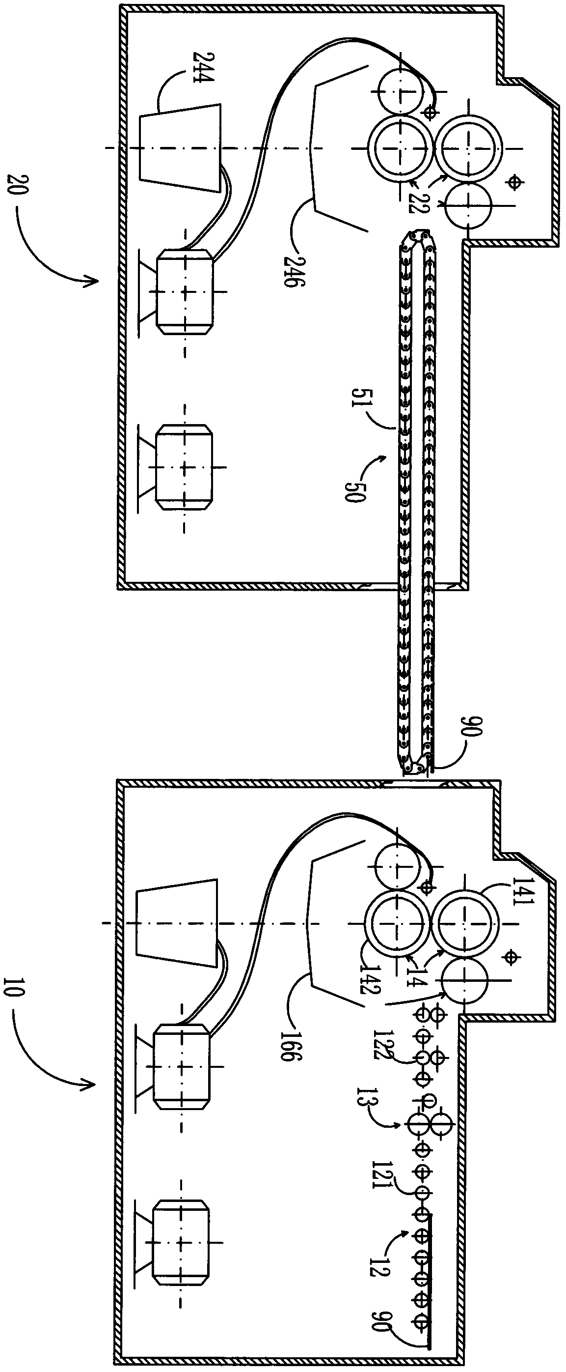
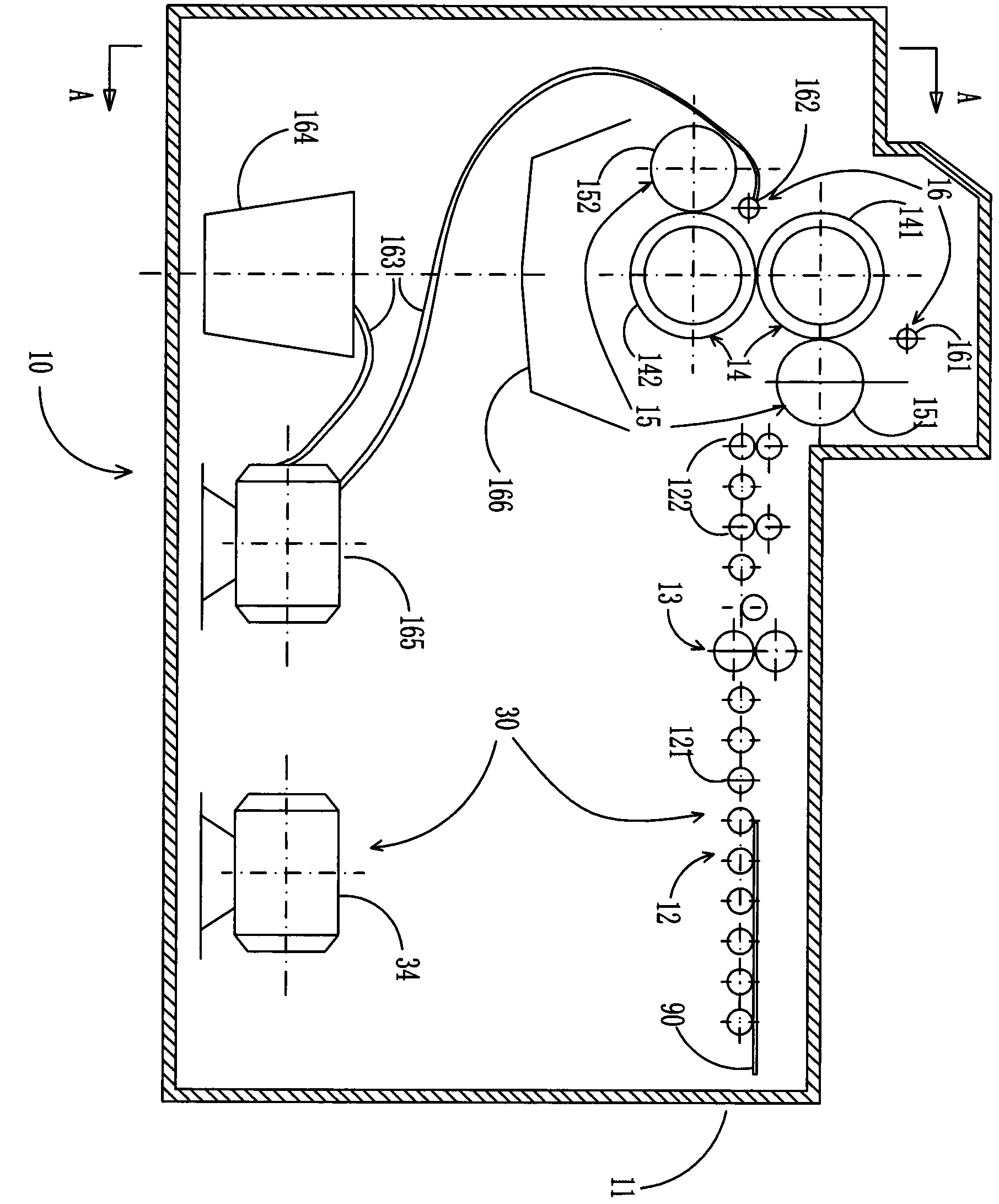
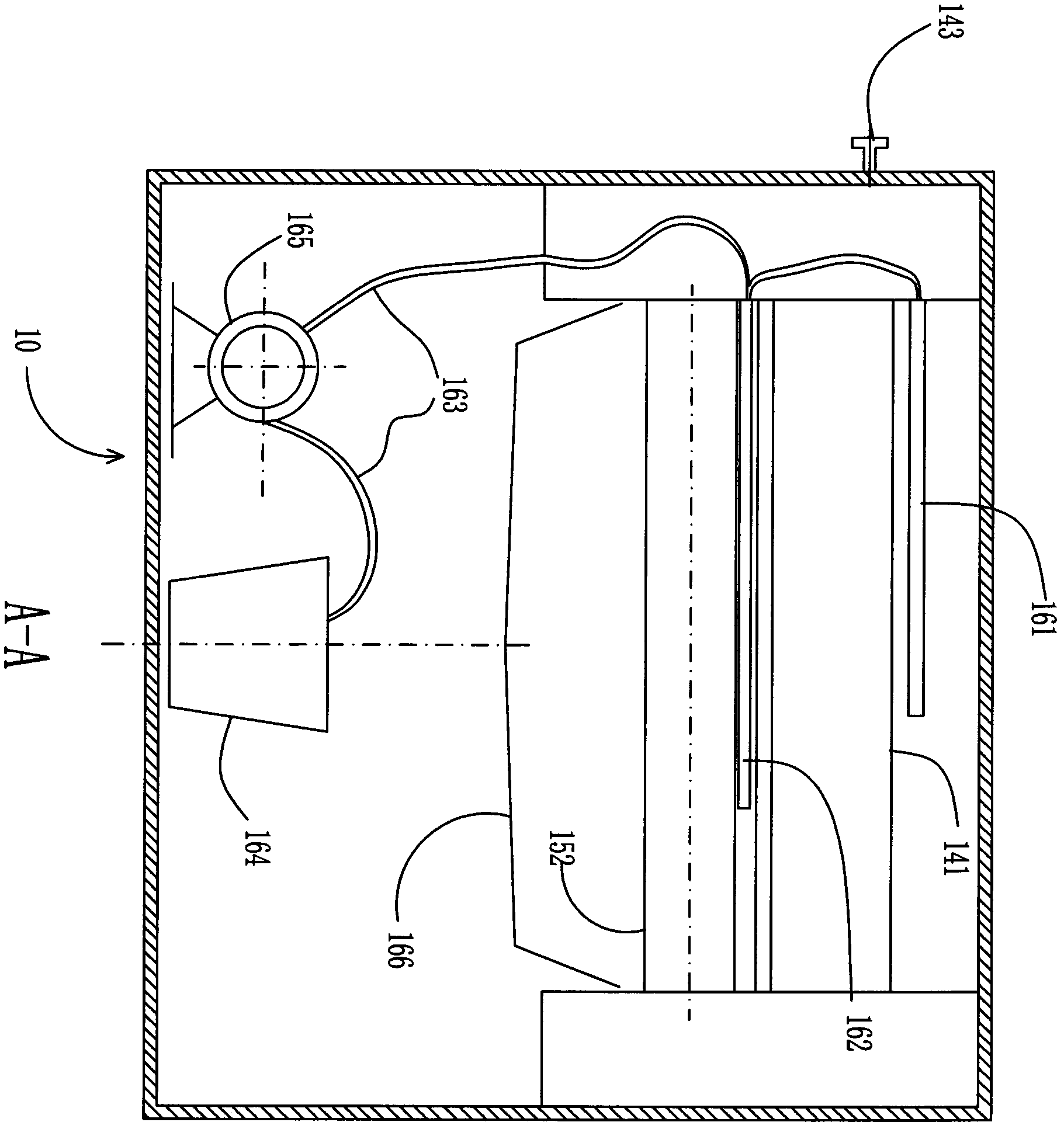
[0030] refer to Figure 1 ~ Figure 4 , take a double-sided circuit board that has been formed with a circuit pattern by etching, the thickness of the copper clad on the circuit board is 36 microns, and send the circuit board 90 into the first solder resist oil coating device 10. like figure 1 , the wiring board 90 is placed at the front end of the coating device 10 ( figure 1 On the roller type feeding mechanism 12 on the right side of the middle), the circuit board 90 is conveyed forward by the roller type feeding mechanism 12, and when passing through the dust sticking wheel 13, the dust sticking wheel 13 sticks and removes the dust on the circuit board 90 , and the circuit board 90 is sent between the first upper coating roller 141 and the first lower coating roller 142 of the first coating roller assembly by two sets of feeding rollers 122, and the first upper spraying roller of the first oil spray assembly The solder resist oil sprayed from the oil pipe 161 and the firs...

Embodiment 2

[0044] The basic steps and the coating device of the coating process of solder resist oil are the same as in Example 1, the difference is that the thickness of the copper clad of the circuit board used is 50 microns, after the first coating of solder resist oil, after measurement, the The thickness of the solder resist oil on the surface of the circuit board in the area with dense lines is 5 microns, and the thickness of the solder resist oil on the surface of the circuit board in other areas is 13 microns. After the second coating, the thickness of the solder resist oil on the surface of the circuit board in the densely populated area is 15 microns, and the thickness of the solder resist oil on the surface of the circuit board in other areas is 21 microns, which has reached the specified requirements.


PUM


Abstract

The invention provides printed circuit board solder resist ink coating technology and a coating apparatus. The coating technology comprises the following steps: a. coating solder resist ink at two sides of a circuit board for the first time by a first resist ink coating apparatus; b. coating the solder resist ink at two sides of the circuit board for the second time by a second resist ink coating apparatus, and using the solder resist ink to cover all lines and copper faces on the circuit board; c. drying the circuit board which goes through second solder resist ink coating. The coating apparatus comprises the first solder resist ink coating apparatus, the second solder resist ink coating apparatus, and a conveying mechanism provided between the first solder resist ink coating apparatus and the second solder resist ink coating apparatus. According to the coating technology and the coating apparatus, labor intensity of production personnel is substantial reduced, screen printing materials is saved, production cost is reduced, and labor productivity is effectively raised.

Description

【Technical field】 [0001] The invention relates to a production process and device of a printed circuit board, and is characterized in that it relates to a coating process and a coating device of solder resist oil for a printed circuit board. 【Background technique】 [0002] In people's lives, printed circuit boards (PCBs) are almost everywhere, and they are used in all electronic devices we can see, ranging from electronic watches, calculators, general-purpose computers, to computers, electronic communication equipment, military Weapon systems, etc., as long as there are electronic components such as integrated circuits, PCBs are used for electrical interconnection between them. Printed circuit boards are formed by setting conductive patterns for electrical connections between electronic components on an insulating substrate, and its manufacturing process is relatively complicated. In the processing technology of printed circuit boards, except for the connection points and t...

Claims


Application Information

Patent Timeline
Patent Type & Authority Applications(China)
IPC IPC(8): H05K3/28
Inventor 陈国富
Owner 陈国富
Learn More