
Millimeter wave micro-strip antenna and manufacturing method thereof

A technology of microstrip antenna and millimeter wave, which is applied in the field of millimeter wave wireless communication and antenna, can solve the problems of difficult direct bonding of metals and fine processing of metal thin films, and achieve the effect of improving radiation efficiency and signal gain and reducing costs

Inactive Publication Date: 2012-01-18
TSINGHUA UNIV
View PDF3 Cites 13 Cited by
  • Summary
  • Abstract
  • Description
  • Claims
  • Application Information

AI Technical Summary

Problems solved by technology

[0006] In the millimeter wave frequency band, on the one hand, the metal lines of the microstrip antenna have become very fine, and the metal must be patterned by the conventional photolithography technology in the microelectronics process; on the other hand, in order to reduce loss, improve efficiency and gain Usually tend to choose a thinner substrate, and plastic materials such as polyethylene or polypropylene are soft, so the prior art cannot use the photolithography technology in the microelectronics process to directly fine-tune the metal film with the above-mentioned plastic thin layer as the substrate. processing; in addition, they are all difficult-to-bond materials, which are difficult to bond directly with metal

Method used


Image

  • Millimeter wave micro-strip antenna and manufacturing method thereof
  • Millimeter wave micro-strip antenna and manufacturing method thereof
  • Millimeter wave micro-strip antenna and manufacturing method thereof

Examples


Embodiment Construction

[0032] The specific implementation manners of the present invention will be further described in detail below in conjunction with the accompanying drawings and embodiments. The following examples are used to illustrate the present invention, but are not intended to limit the scope of the present invention.

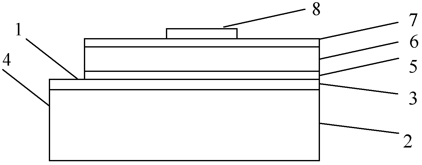
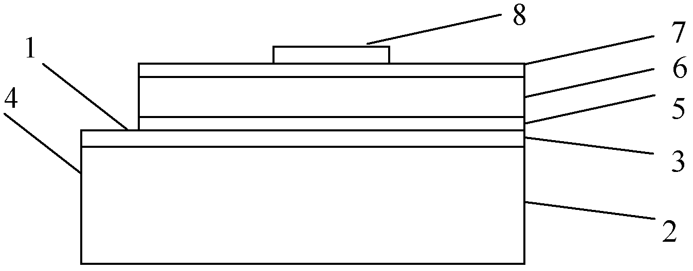
[0033] Such as figure 1 As shown, the millimeter-wave microstrip antenna of the present invention includes:

[0034] The antenna substrate 1 includes arranged from bottom to top: a printed circuit copper clad laminate 4, a lower layer of epoxy resin 5, a polypropylene or polyethylene plastic layer 6 and an upper layer of epoxy resin 7; the millimeter wave microstrip antenna includes a layer or The printed circuit copper clad laminate 4 is multi-layered. The printed circuit copper clad laminate 4, the lower layer resin 5, the polypropylene or polyethylene middle layer resin 6 and the upper layer resin 7 are bonded sequentially. The printed circuit copper clad laminate 4 ...


PUM


Abstract

The invention discloses a millimeter wave micro-strip antenna and a manufacturing method thereof, relating to the technical fields of millimeter wave wireless communication and antennae. The millimeter wave micro-strip antenna comprises an antenna substrate (1) and a graphic metal film (8), wherein the antenna substrate (1) comprises a printed circuit copper-clad plate (4), lower layer epoxy resin (5), a polypropylene or polyethylene plastic layer (6) and upper layer epoxy resin (7) which are arranged from bottom to top; the graphic metal film (8) is positioned on the surface of the lower layer epoxy resin (5); and the printed circuit copper-clad plate (4) comprises an epoxy resin substrate (2) and a copper foil (3). In the invention, the substrate of the millimeter wave micro-strip antenna is manufactured by taking the printed circuit copper-clad plate which consists of the resin substrate and the copper foil on the surface of the resin substrate as well as a layer of common plastic as main bodies, so that the radiance efficiency and signal gain of the micro-strip antenna can be increased, and the cost of the antenna can be lowered.

Description

technical field [0001] The invention relates to the technical field of millimeter wave wireless communication and antennas, in particular to a millimeter wave microstrip antenna and a preparation method thereof. Background technique [0002] Miniaturization, integration, and broadband have always been the development direction of wireless mobile communication systems, and the expansion of its frequency band to the millimeter wave frequency band is an inevitable trend in future development. [0003] As the frequency band increases, the size of the antenna will decrease proportionally. Due to the advantages of small size, light weight, low profile, and easy conformity with the carrier, microstrip antennas will play a more important role in wireless mobile communications in the millimeter wave band. In the design of microstrip antenna, its radiation efficiency and signal gain are important parameters to measure the performance of microstrip antenna. Improving the radiation ef...

Claims


Application Information

Patent Timeline
Patent Type & Authority Applications(China)
IPC IPC(8): H01Q1/38H01Q13/08
Inventor 岳瑞峰罗俊陆斌王燕
Owner TSINGHUA UNIV
Learn More