Method and device for measuring angle of flange

A measuring device and edge angle technology, applied in angle/taper measurement and other directions, can solve problems such as accuracy problems

Active Publication Date: 2012-01-18
中浙高铁轴承有限公司
View PDF3 Cites 5 Cited by
  • Summary
  • Abstract
  • Description
  • Claims
  • Application Information

AI Technical Summary

Problems solved by technology

[0010] In order to solve the problem of the accuracy of measuring the angle between the rib and the reference end face in the production of cylindrical roller bearings, the purpose of the present invention is to provide a method and device for measuring the angle of the rib, combined with the instrument, the angle can be measured after the instrument is adjusted and confirmed. High accuracy and good stability

Method used


Image

  • Method and device for measuring angle of flange
  • Method and device for measuring angle of flange
  • Method and device for measuring angle of flange

Examples


Embodiment Construction

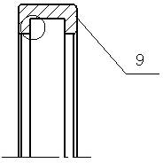
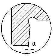
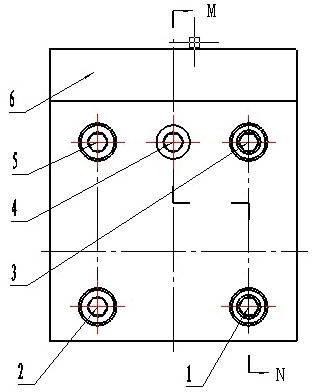
[0033] As shown in Figures 1, 2, and 3, a straightness measuring device for measuring the angle of the rib is composed of a vertical plate 7 provided with an elastic slot 8 and a vertical horizontal plate 6 to form an elastic hinge type measuring device. 7 is provided with a fixed surface "A" surface, and the horizontal plate 6 is provided with a "B" surface perpendicular to the "A" surface on the vertical plate 7; The "C" surface of the "A" surface; the "A" surface of the vertical plate 7 is provided with two fixed connection screws 1, 2, and the upper "C" surface of the two fixed connection screws is provided with the "B" surface reversed. Two adjusting screws 3, 5 for clockwise fine-tuning, and an adjusting screw 4 for clockwise fine-tuning of the "B" face is arranged between the two adjusting screws 3, 5 on the "C" face.

[0034] The "C" surface on the vertical plate 7 is 1 mm lower than the "A" surface, and the elastic slotted hole 8 is arranged at the intersection of the...


PUM


Abstract

The invention relates to the technical field of bearing measurement and discloses a method and device for measuring the angle of a flange; the method comprises the following steps of: converting the angle measurement into the straightness measurement, using a sine instrument for direct measurement when a is larger than or equal to 45 degrees or is less than or equal to 90 degrees, enabling the end surface of a workpiece 9 to be close to the locating 'D' surface of the vertical stand column; adopting the 'B' surface of a transverse plate of a straightness measurement device when a is larger than or equal to 0 degrees or is less than or equal to 45 degrees, placing a block gauge 13 under a locating stand column 11, converting the locating 'D' surface of the stand column into a locating surface which is parallel to the guide rail 12, enabling the end surface of the workpiece to be close to the 'B' surface of the transverse plate of the straightness measurement device, and using a gauge needle on a measuring gauge 14 on a guide rail 12 for contacting a measured surface, wherein the height deviation indicated by the measuring gauge is an included angle error between an inclined surface and the reference end surface; and the invention can enable the accuracy of measurement on the included angel between the flange and a reference end surface in the cylinder roller bearing production process to be higher and the stability to be better. The invention is not affected by the size of chamfering of the flange, the parallel error of the flange and the experience of survey crews.

Description

technical field [0001] The invention relates to the technical field of bearing measurement, in particular to a method and device for measuring a rib angle of a cylindrical roller bearing. It is suitable for the accurate measurement of the angle between the rib of the cylindrical roller bearing ring and the reference end face, and it is also suitable for the accurate measurement when the angle between the arbitrary shape surface and the reference end face is less than 45°. Background technique [0002] At present, the ribs of cylindrical roller bearings need to process the rib bevels. As shown in Figure 1, the bevel angle of the rib is a small angle between the rib and the reference end surface, and the included angle is determined by the design between 10′~1°. At present, there are three general methods for measuring the rib bevel angle of cylindrical roller bearings: [0003] Method 1: Measuring the inner and outer difference of the rib: Positioning with the reference end...

Claims


Application Information

Patent Timeline
IPC IPC(8): G01B5/24B23P15/00
Inventor 方芳田永焜李红杨瑞君张军
Owner 中浙高铁轴承有限公司
Why Eureka
Try Eureka