
Small cantilever-type fully-automatic loading and unloading crane pipe

A fully automatic, cantilever-type technology, applied in packaging, dispensing devices, transportation and packaging, etc., can solve the problems that threaten the safety production of petrochemical enterprises, easily generate sparks in transmission, and affect the health of loading personnel.

Inactive Publication Date: 2013-03-13
LUOYANG XINPU PETROCHEM EQUIP
View PDF1 Cites 0 Cited by
  • Summary
  • Abstract
  • Description
  • Claims
  • Application Information

AI Technical Summary

Problems solved by technology

Chinese Patent No. 94204828.8 discloses a pneumatic crane tube, which uses an air motor as the driving mechanism, and utilizes the transmission structure of the worm wheel and the worm, so as to realize the alignment of the crane tube with the tank mouth of the tanker. This structure replaces manual operation. It is advanced to a certain extent, but the transmission between the worm gear and the worm is prone to sparks during the working process. Therefore, this pneumatic crane tube is not suitable for work in flammable and explosive areas, and the air motor is prone to failure and noise. It is very large, which not only seriously threatens the safe production of petrochemical enterprises, but also affects the health of loading personnel

Method used


Image

  • Small cantilever-type fully-automatic loading and unloading crane pipe
  • Small cantilever-type fully-automatic loading and unloading crane pipe
  • Small cantilever-type fully-automatic loading and unloading crane pipe

Examples


Embodiment 1

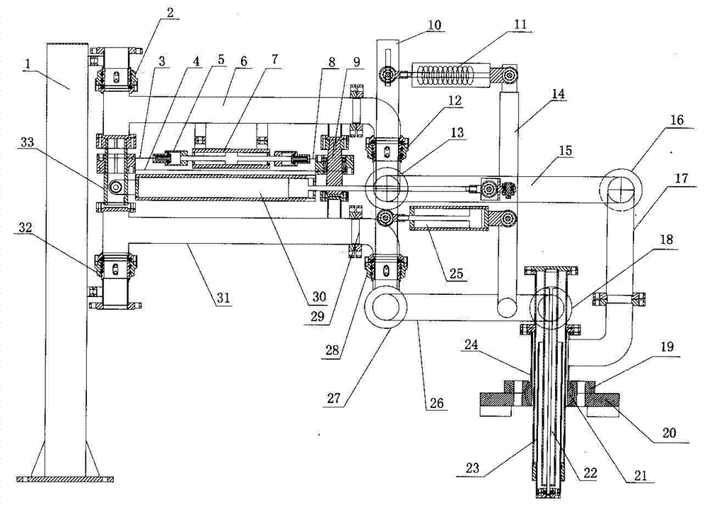
[0023] Such as figure 1 As shown, the cantilever type fully automatic loading and unloading small crane tube includes a column 1, a liquid phase crane tube, a gas phase crane tube and a vertical tube 24, and the liquid phase crane tube is composed of a flange 29, an elbow, and a second horizontal The inner arm 31 and the outer arm 26 which are connected together by the rotary joint 28 and the first up and down rotary joint 27 are formed. The joint 18 is connected with the vertical pipe 24, and a spring cylinder balance device is installed on the outside of the outer arm; the spring cylinder balance device includes a connecting plate A 10, a connecting plate B 14 and a spring cylinder 11, and the lower end of the connecting plate A 10 is connected to the first up and down rotation On the joint, the lower end of the connecting plate B 14 is connected to the outer arm 26, the connecting plate A and the connecting plate B are vertically parallel, the spring cylinder 11 is arranged...

Embodiment 2

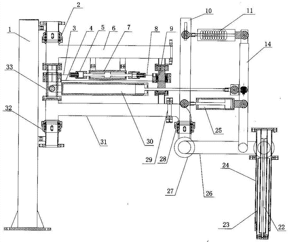
[0035] Such as figure 2 As shown, the cantilever type fully automatic loading and unloading small crane tube includes a column 1, a liquid phase crane tube and a vertical tube 24, and the liquid phase crane tube is composed of a flange 29, an elbow, a second horizontal rotary joint 28, The inner arm 31 and the outer arm 26 that are connected together by the first up and down rotary joint 27 are formed, the head end of the inner arm 31 is connected with the column 1 through the first horizontal rotary joint 32, and the tail end of the outer arm 26 is connected with the vertical column through the second up and down rotary joint 18. The tube 24 is connected, and a spring cylinder balancing device is installed on the outer side of the outer arm; the spring cylinder balancing device includes a connecting plate A 10, a connecting plate B 14 and a spring cylinder 11, and the lower end of the connecting plate A 10 is connected to the first upper and lower rotary joint, connected The...

Embodiment 3

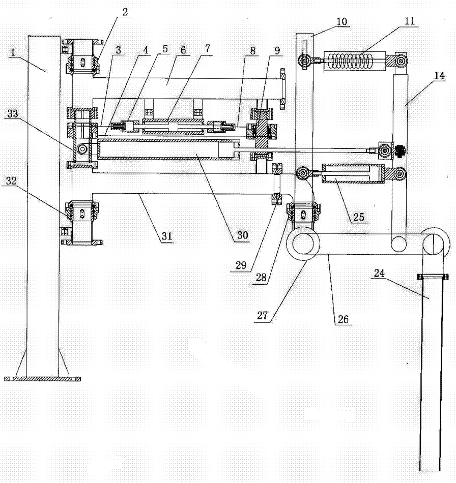
[0040] Such as image 3 As shown, the structure of the cantilever type fully automatic loading and unloading small crane tube is basically the same as that of the small crane tube in Embodiment 2, the only difference is that there is no telescopic tube inside the vertical tube 24, and a vertical telescopic cylinder that controls the vertical movement of the telescopic tube .

[0041] The working process of the cantilever type fully automatic loading and unloading of the small crane tube in this embodiment is the same as the operation process of the liquid phase crane tube controlled by the bidirectional cylinder, the horizontal telescopic cylinder and the lifting cylinder in the first embodiment.

[0042] In this embodiment, the cantilever-type fully automatic loading and unloading small crane tube is suitable for petroleum and chemical enterprises to pack crude oil, residual oil, bitumen and other liquids with high density, non-volatile and non-polluting to the environment. ...


PUM


Abstract

The invention discloses a small cantilever-type fully-automatic loading and unloading crane pipe, which comprises an upright post, a liquid-phase crane pipe and a vertical pipe, wherein the liquid-phase crane pipe is formed from an inner arm and an outer arm which are connected together, the head end of the inner arm is connected with the upright post, the tail end of the outer arm is connected with the vertical pipe, and a spring-cylinder balancing device is installed at the outer side of the outer arm; a horizontally-telescopic cylinder for controlling the outer arm to rotate in a horizontal direction and a bidirectional cylinder for controlling the inner arm to rotate in the horizontal direction are installed at the upper part of the inner arm in the horizontal direction, one end of the horizontally-telescopic cylinder is connected with the inner arm through a steering assembly, a piston rod at the other end is connected with the outer arm or is connected with the outer arm through the spring-cylinder balancing device, the A end of the piston rod of the bidirectional cylinder is connected with the steering assembly through a transmission mechanism, and the B end of the piston rod of the bidirectional cylinder is connected with a guiding assembly which is installed at the upper part of the inner arm through the transmission mechanism; and a lifting cylinder for controlling the outer arm to move in an upright direction is installed on the spring-cylinder balancing device. Through the small cantilever-type fully-automatic loading and unloading crane pipe, the automatic alignment of the crane pipe and a tank-car tank opening is realized, and the work efficiency is greatly improved.

Description

technical field [0001] The invention belongs to the technical field of loading and unloading fluid materials on railway tank cars, and in particular relates to a cantilever type automatic loading and unloading small crane tube, which is used for loading and unloading flammable and explosive liquids on railway tank cars. Background technique [0002] Crane tube is the main equipment in the process of liquid loading and unloading in the petrochemical industry. At present, the crane tube is mainly composed of a column, a horizontal tube, a vertical tube, a rotary joint and a moment balance device to form a liquid phase crane tube, and the crane tube with the function of oil and gas recovery is based on the above liquid phase crane tube structure. Gas-phase crane tubes with basically the same branch structure. In the prior art, most of the crane pipes are manually manipulated to align them with the tank mouth of the tanker. In this way, the labor intensity of the operator is hi...

Claims


Application Information

Patent Timeline
Patent Type & Authority Patents(China)
IPC IPC(8): B67D7/38
Inventor 刘国良王清朝陈方李红伟盖振海张长轩张敬博
Owner LUOYANG XINPU PETROCHEM EQUIP
Learn More