
Vehicle body correcting machine and control system mounted on base of correcting machine

A control system and correction machine technology, applied in the direction of lifting devices, lifting frames, etc., can solve the problems of increasing secondary installation costs, increasing site area, intermittent control process, etc., and achieve the goal of saving manpower, simple layout, and shortening the movement drop Effect

Inactive Publication Date: 2013-03-20
烟台三重技术股份有限公司
View PDF6 Cites 2 Cited by
  • Summary
  • Abstract
  • Description
  • Claims
  • Application Information

AI Technical Summary

Problems solved by technology

Its main defects are: 1. The main control function is only up and down, and other related functions are missing, requiring manual supplementation, and the control process is intermittent; 2. Occupying the working channel increases the site area; 3. Oil, gas and pipeline crossing work The channel is easy to be damaged; 4. It can only be operated at a fixed point or within a limited range, often requiring additional assistants, and there are certain safety hazards for the vigorous stretching operation that needs to be far away from the work area; 5. When the equipment is delivered, due to the control cabinet and the main machine Separation, requiring additional costs for packaging, shipping, and post-sale secondary installation

Method used


Image

  • Vehicle body correcting machine and control system mounted on base of correcting machine
  • Vehicle body correcting machine and control system mounted on base of correcting machine
  • Vehicle body correcting machine and control system mounted on base of correcting machine

Examples


Embodiment Construction

[0054] Referring to the accompanying drawings, specific embodiments of the present invention are given below to further describe the present invention.

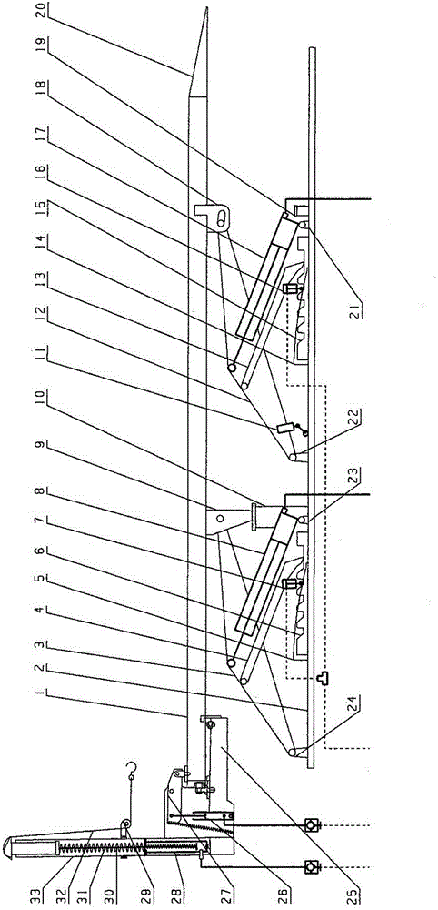
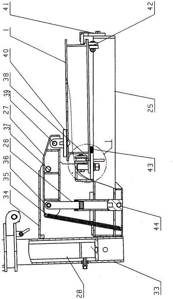
[0055] Such as figure 1 , the car body correction machine of the present invention includes a flexible lifting mechanism and a pull tower, and the pull tower is locked and installed on the platform 1 including the flexible lifting mechanism through the pull tower quick locking mechanism.

[0056] The pull tower comprises a pull tower cross arm 25 and a tower column 33 installed on the pull tower cross arm 25, a stretching oil cylinder 28 is installed at the inner bottom of the tower column 33, and the stretch oil cylinder 28 is connected with a push rod 30. A ring sleeve 29 is installed on the outer circle of the ring sleeve 29, and the stretch chain 32 with a pull hook passes through the sprocket wheel on the ring sleeve 29, and is fixed on the push rod 30 through the chute on the top surface of the push rod 30, and also inc...


PUM


Abstract

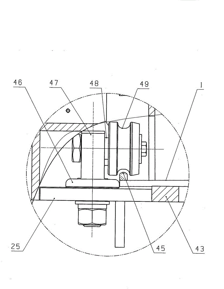
The invention relates to a vehicle body correcting machine and a control system mounted on a base of the correcting machine, the vehicle body correcting machine comprises a lifting mechanism and a drawing tower, and a front position-limiting pile and a rear position-limiting pile are respectively fixedly mounted on the base of the lifting mechanism. The vehicle body correcting machine further comprises a locking arm for locking the drawing tower on the lifting mechanism, the locking arm is connected with an upper frame which is fixedly mounted on a tower column through a second articulated shaft at the middle part of the locking arm, and the front end of the locking arm is connected with a floating locking head through a first articulated shaft. The upper end of a locking oil cylinder is connected with the rear end of the locking arm through a third articulated shaft. A locking mechanism comprises two rolling wheels for matching with a platform track, the rolling wheels are connected with a revolution shaft through rotation shafts, the revolution shaft is mounted on a cross arm of the drawing tower and a directional wheel is further mounted on the revolution shaft. The control system is mounted on the correcting machine, the vehicle body correcting machine integrates parallel lifting and oblique lifting of a platform, locking of the drawing tower and the functions of the drawing tower into a whole and is controlled by virtue of remote control keys, and thus the automatic and continuous correction operation is further realized.

Description

technical field [0001] The invention relates to a car body correction machine and its control system. [0002] The car body correction machine of the present invention includes a flexible lifting mechanism, and the flexible lifting mechanism has two functional modes of parallel lifting and tilting lifting, and can perform rigid horizontal lifting when it is greater than or equal to the minimum horizontal height, and can perform rigid horizontal lifting when it is less than the horizontal At the lowest height, flexible tilting and lifting can be performed, and the conversion of the two modes is continuous. Background technique [0003] The car body correction machine includes a lifting mechanism and a pulling tower, and the pulling tower is locked and installed on the platform of the lifting mechanism through a locking device. [0004] The lifting mechanism is one of the main functional parts of the car body correction machine. It is used to lift the working platform of the ...

Claims


Application Information

Patent Timeline
Patent Type & Authority Patents(China)
IPC IPC(8): B21D1/12B66F7/08
Inventor 李宏张令浩崔建平郭胜利张吉成牟德虎
Owner 烟台三重技术股份有限公司
Learn More