
Method for removing impurity oxide layer from polluted accelerating tube

A technology of accelerating tube and oxide layer, which is applied in chemical instruments and methods, cleaning methods and utensils, cleaning hollow objects, etc., can solve the problems of high processing accuracy and smoothness, pulse power loss of accelerating tube, complex cavity structure, etc. Achieve significant social and economic benefits, recover economic losses, and have a wide range of applications

Inactive Publication Date: 2013-04-17
NANJING UNIV
View PDF4 Cites 0 Cited by
  • Summary
  • Abstract
  • Description
  • Claims
  • Application Information

AI Technical Summary

Problems solved by technology

[0003] The accelerating tube is welded by dozens of holes and bowl-shaped cavities. Because different types of accelerators have different energies, the length of the accelerating tubes of the accelerators is also different. The total length is about 2 m Left and right, the structure of the cavity is particularly complex, and the processing accuracy and finish are high. After welding, a dead angle is formed in the cavity of the acceleration tube. No matter the acceleration tube is in the working or non-working stage, the accelerating tube should always be in a vacuum protection state to prevent the atmosphere, Impurities enter the cavity until the cavity is oxidized, causing the pulse power of the accelerating tube to be lost by the cavity wall, and eventually the main indicators of the accelerator are greatly reduced, or even unusable, so it needs to be replaced
On the one hand, due to the long-term operation of the accelerator, air enters the cavity of the accelerator tube during maintenance, and after repeated accumulations, it causes oxidation in the cavity of the accelerator tube and reduces the index
On the other hand, for accelerator equipment that has been aging and updated, the accelerator tubes are also treated as scrap products, or stored in scrap warehouses
[0004] Due to the high technical content of the accelerating tube, the processing is difficult. An accelerating tube needs several tons of oxygen-free copper, which is expensive. The cost of an accelerating tube is 400,000-500,000, and the processing cycle is long and difficult.

Method used


Image

  • Method for removing impurity oxide layer from polluted accelerating tube
  • Method for removing impurity oxide layer from polluted accelerating tube
  • Method for removing impurity oxide layer from polluted accelerating tube

Examples


Embodiment Construction

[0019] A method for decontaminating the oxide layer of the polluted post-acceleration tube of the present invention, comprising the following steps:

[0020] 1. Fix the acceleration tube vertically, place the axis of the acceleration tube perpendicular to the horizontal plane (the neutral acceleration tube already in use meets the requirements), and the input end of the acceleration tube faces upward.

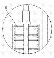
[0021] 2. Put the bottom of the cleaning tool in the plastic tank 8 equipped with cleaning liquid, pump the cleaning liquid into the metal pipe 1 of the cleaning tool through the water pump 3; insert the lower end of the metal pipe of the cleaning tool into the acceleration tube 6, and accelerate The inner wall of the lumen is cleaned. figure 1 It is a schematic diagram of cleaning tool connection in the present invention, figure 1 Middle 7 is connecting flange. The connecting flange fixes the metal tube 1 at the center of the cavity of the accelerating tube. figure 2 It is...


PUM


Abstract

The invention discloses a method for removing an impurity oxide layer from a polluted accelerating tube. The method comprises the following steps: vertically fixing the accelerating tube, placing the accelerating tube by enabling the axial line of the accelerating tube to be vertical to the horizontal plane, and enabling the input end of the accelerating tube to be upward; placing the lower part of a cleaning tool in a plastic tank equipped with cleaning solution, and pumping the cleaning solution into a metal tube of the cleaning tool through a water pump; and slowly moving down and rotatingthe metal tube of the cleaning tool, cleaning the inner wall of the cavity of the accelerating tube, replacing the cleaning solution, flushing repeatedly, and flushing impurities on the inner wall ofthe cavity of the accelerating tube and the oxide layer with the cleaning solution jetted out of small holes of the metal tube till the impurities and the oxide layer are treated to be qualified. Thecleaning tool and the reasonable chemical treatment method are adopted in the method for removing the impurities and the oxide layer from the accelerating tube and enabling the accelerating tube to be in line with the using requirements, so that even the accelerating tube which is scrapped can be re-used and the waste is turned into a valuable product.

Description

technical field [0001] The invention relates to a cleaning method for an electron linear accelerating tube, in particular to a method for removing impurities and oxide layers from the polluted accelerating tube. Background technique [0002] The acceleration tube is the core component of the medium and high energy electron linear accelerator, which includes traveling wave and standing wave linear accelerators. The products are divided into industrial radiation accelerators, medical accelerators, flaw detection accelerators, etc. according to their functions. Radiotherapy for tumor patients, inspection of customs articles, industrial inspection, and testing have made important contributions. The application of civil nuclear technology has been included in the high-tech fields supported by the state. [0003] The accelerating tube is welded by dozens of holes and bowl-shaped cavities. Because different types of accelerators have different energies, the length of the accelerati...

Claims


Application Information

Patent Timeline
Patent Type & Authority Patents(China)
IPC IPC(8): B08B9/04
Inventor 杭德生高山宝
Owner NANJING UNIV
Learn More