
Wireless network real-time differential global positioning system (GPS) positioned flying hot air balloon

A GPS positioning and real-time differential technology, used in satellite radio beacon positioning systems, balloon vehicles, radio wave measurement systems, etc., can solve problems such as limited application and development, danger to the lives of flight personnel, and inability to accurately locate flight altitude and position. , to achieve the effect of real-time control

Inactive Publication Date: 2012-01-04
JIANGSU UNIV
View PDF5 Cites 5 Cited by
  • Summary
  • Abstract
  • Description
  • Claims
  • Application Information

AI Technical Summary

Problems solved by technology

[0002] At present, the commonly used hot air balloons do not have a direction control system, an accurate lifting system, a speed control system and a positioning system. It is determined that the height and position of the flight cannot be accurately positioned, and unmanned intelligent flight cannot be realized. The flight personnel must fly with the hot air balloon, and the flight personnel control the flight status of the hot air balloon.
When the weather conditions are bad and the operation is improper, it will bring life danger to the flight crew
Therefore, the current hot air balloons limit its application and development, and cannot bring due benefits to society.

Method used


Image

  • Wireless network real-time differential global positioning system (GPS) positioned flying hot air balloon
  • Wireless network real-time differential global positioning system (GPS) positioned flying hot air balloon
  • Wireless network real-time differential global positioning system (GPS) positioned flying hot air balloon

Examples


Embodiment Construction

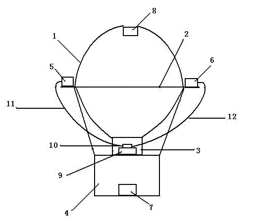
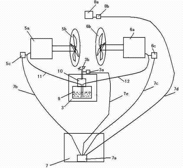
[0022] Such as figure 1 As shown, the hot air balloon of the present invention includes a sphere 1 , and a support bar 2 is fixedly connected laterally at the largest diameter of the sphere 1 , and both ends of the support bar 2 pass through the sphere 1 . Before the hot air balloon is launched into the air, the first and second speed direction devices 5 and 6 are respectively fixed on the two ends of the support bar 2 . The deflation speed control device 8 is fixedly installed on the top of the spheroid 1. Directly below the sphere 1 is provided with a combustion power device 3 , and directly below the combustion power device 3 a loading basket 4 is fixed, and an intelligent control system 7 is provided at the bottom of the loading basket 4 . A fuel tank 9 is fixed in the combustion power unit 3, and a micropump 10 is fixedly connected to the fuel tank 9, and the micropump 10 has three output ports. The first oil delivery pipe 11 communicates with the first speed dire...


PUM


Abstract

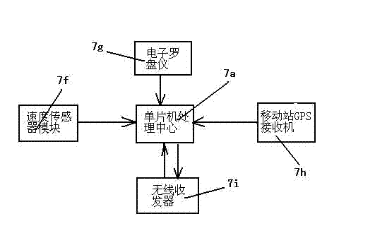
The invention discloses a wireless network real-time differential global positioning system (GPS) positioned flying hot air balloon. A combustion power device is arranged right below the balloon body, speed direction devices are fixedly connected to two ends of a supporting lever respectively, a deflating speed control device is arranged above the top of the balloon body, an intelligent control system is arranged at the lower part of a carrying basket, a micro pump with three output ports is arranged on a fuel tank, an oil delivery pipe is communicated with the speed direction devices and twooutput ports of the micro pump, and the third output port of the micro pump is connected with a combustion furnace; the intelligent control system consists of a singlechip processing center and a speed sensor module, an electronic compass, a mobile station GPS receiver and a wireless transceiver respectively connected with the singlechip processing center; the mobile station GPS receiver is used for receiving satellite positioning information, the wireless transceiver is used for receiving differential information broadcast by the base station GPS receiver, and the base station GPS receiver is used for receiving the satellite positioning information and acquiring the differential information; and accurate positioning and unmanned intelligent flying are realized by combining wireless network real-time differential GPS positioning technology and singlechip control.

Description

technical field [0001] The invention relates to a hot-air balloon, in particular to a hot-air balloon that adopts GPS positioning and flight. Background technique [0002] At present, the commonly used hot air balloons do not have a direction control system, an accurate lifting system, a speed control system and a positioning system. For unmanned intelligent flight, the pilot must fly with the hot air balloon, and the pilot controls the flight status of the hot air balloon. When the weather condition is bad and the operation is improper, it will bring life danger to the flight crew. Therefore, present hot-air balloon has limited its application and development, can not bring due benefit to society. Contents of the invention [0003] In order to solve the above problems, the present invention provides a wireless network real-time differential GPS positioning flying hot air balloon, which can realize unmanned intelligent flight, automatic control of flight direction, auto...

Claims


Application Information

Patent Timeline
IPC IPC(8): B64B1/40G01S19/42
Inventor 张荣标黄义振杨宁
Owner JIANGSU UNIV
Learn More