
communication device

A technology for communication devices and equipment information, which is applied in the direction of selection devices, telemetry/remote control selection devices, signal transmission systems, etc., and can solve problems such as unconsidered, undisclosed or hinted, complicated operations, etc.

Active Publication Date: 2011-12-28
SUN PATENT TRUST
View PDF5 Cites 60 Cited by
  • Summary
  • Abstract
  • Description
  • Claims
  • Application Information

AI Technical Summary

Problems solved by technology

That is, when selecting a controlled device, it is necessary to perform multiple operations on the communication device so that it functions as a remote controller of the controlled device, which has the problem of complicated operations.
[0014] In addition, in the structure of the above-mentioned Patent Document 2, it is necessary to prepare an operation table corresponding to the electronic device to be operated.
That is, there is a problem that whenever the number of electronic devices that the user wants to control increases, it is necessary to prepare an operation table corresponding to the electronic device.
Furthermore, in the case of operating a plurality of controlled devices, there is no disclosure or hint about the method of logging in the operator's selection object and the command for the device corresponding to the selection object.

Method used


Image

  • communication device
  • communication device
  • communication device

Examples


Embodiment approach 1

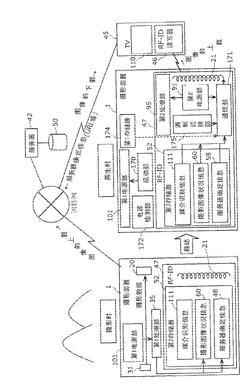
[0339] Embodiment 1 of the present invention will be described. figure 1 A conceptual diagram showing the present invention. Here, a communication system composed of a photographing device (camera, camera) 1 , a TV (television) 45 , and a server 42 is shown. In this figure, the left side shows the situation at the time of shooting, and the right side shows the situation when the shot image is reproduced.

[0340] The photographing device 1 is an example of a communication device (here, a digital camera) related to the present invention, and includes a first power supply unit 101, an image processing unit 31, a second antenna 20, and a first processing unit 35 as components related to photographing. , the second memory 52 storing medium identification information 111 , captured image status information 60 , and server identification information 48 , and the antenna 21 for RF-ID. In addition, this photographing device 1 includes, as constituent units related to playback, a fir...

Embodiment approach 2

[0526] Next, the specific operation of the communication system of the present invention, that is, a communication system that uploads an image acquired by a camera and then downloads and displays the image on a TV with simple operations, will be described as Embodiment 2. The overall configuration of the communication system is the same as that of the first embodiment.

[0527] exist Figure 40A ~ Figure 40C In , a flow chart showing a series of steps in which the camera (photography device 1) uploads a photo is shown. First, when the camera captures an image (step S5101), it saves the captured image in the third memory (step S5102), and performs update processing of the second memory information (step S5103). This update information will be described later. Next, it is judged by the communication unit whether or not it is possible to connect to the Internet (step S5104), and if it is possible to connect, URL creation processing is performed (step S5105). Details of this p...

Embodiment approach 3

[0640] Embodiment 3 of the present invention will be described.

[0641] First, an overview of Embodiment 3 will be described. Figure 48 It is a schematic configuration diagram of an electronic catalog display system according to Embodiment 3. The electronic catalog display system according to Embodiment 3 has an electronic catalog server information input device 500 equipped with an RF-ID writing unit 501, an electronic catalog notification card 502 equipped with an RF-ID 47, an RF-ID reading unit 504, and a network communication unit 509x. TV45 and electronic catalog server 506 equipped with electronic catalog data database 507 and customer attribute database 508 .

[0642] Electronic catalog server information input device 500 writes electronic catalog server information input from a user (electronic catalog service provider) into RF-ID 47 attached to electronic catalog notification card 502 from RF-ID writing unit 501 . When the user (service user of the electronic cata...


PUM


Abstract

A communication device that can easily correspond to an extended user interface such as a remote controller without complicated operations includes: a device information acquisition unit (203) that acquires device information from a device; a location information acquisition unit (206) that acquires The operation information acquisition unit (212) acquires the operation information based on the equipment information; the storage unit (213) stores the position information as equipment position information indicating the position of the above-mentioned equipment in association with the operation information; the direction sensing unit (207), sensing the direction information of the communication device (102); the pointing space calculation part (208), based on the position information and direction information, calculating the pointing space of the communication device (102); the selection part (209a), determining according to the device position information A device present in the pointing space selects operation information corresponding to the determined device; and an operation information transmitting unit (215) transmits a control signal for operating the device based on the selected operation information.

Description

technical field [0001] The present invention relates to a communication device, and relates to a communication device for providing an extended user interface of a home appliance by using short-distance wireless communication. Background technique [0002] Disclosed is a communication device capable of serving as a remote controller (remote controller) of the device by reading device information from an IC tag of the device using short-range wireless communication and registering operation information corresponding to the read device information use (for example, refer to Patent Document 1). This communication device has an operation unit that can be used as a remote controller for remotely controlling a predetermined controlled device, has an IC tag reading unit that reads device information associated with the controlled device from an IC tag, and stores the device information in association with it. Registering the device information read by the IC tag reading unit with ...

Claims


Application Information

Patent Timeline
IPC IPC(8): H04Q9/00
CPCG08C2201/71G08C17/00G08C2201/32G08C2201/91G08C2201/20
Inventor 大西聪明山冈胜大岛光昭松本通弘大平智亮大坪绍二向井务松下阳介中江宏典山田和范
Owner SUN PATENT TRUST
Learn More