Manual loading and unloading mechanism of workpiece transfer device

A technology of conveying device and loading and unloading mechanism, which is applied in the direction of feeding device, positioning device, storage device, etc., can solve the problem of breakage of the workpiece holding hand 5 and the feeding rod, and achieve the effects of ensuring durability, reducing cost, and restraining breakage.

Active Publication Date: 2011-12-28
欧立机电株式会社
View PDF8 Cites 4 Cited by
  • Summary
  • Abstract
  • Description
  • Claims
  • Application Information

AI Technical Summary

Problems solved by technology

[0011] Therefore, this pressing force acts as an impact force on the connecting portion on the base end side of the workpiece holding hand 5 and repeats the action, thereby causing the second problem of damage to the workpiece holding hand 5 and the feed rod 2.

Method used


Image

  • Manual loading and unloading mechanism of workpiece transfer device
  • Manual loading and unloading mechanism of workpiece transfer device
  • Manual loading and unloading mechanism of workpiece transfer device

Examples


Embodiment Construction

[0063] Next, embodiments of the present invention will be described based on examples.

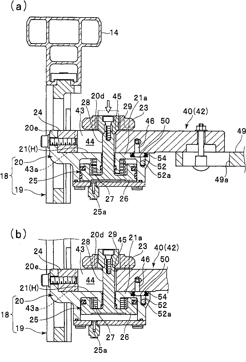
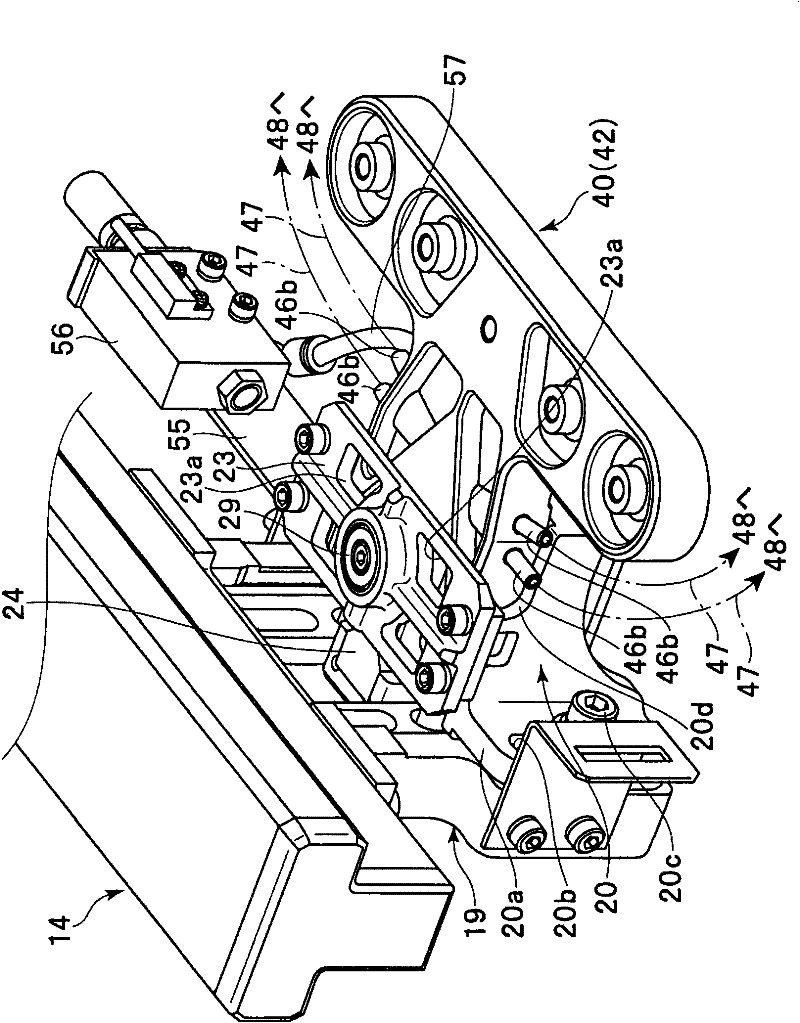
[0064] Figure 1 to Figure 10 A hand loading and unloading mechanism of a workpiece conveying device according to an embodiment of the present invention is shown, figure 1 is a front view of the entire workpiece transfer device, Figure 2 to Figure 8 The hand loading and unloading mechanism of this conveying device is shown.

[0065] exist figure 1 Among them, the workpiece transfer device 10 is the same as the above-mentioned conventional example. For example, it is configured as an industrial robot that is installed in the middle position of a pair of press processing machines (not shown) and moves from one (for example, figure 1 On the left side) the workpiece mounting table (not shown) of the press processing machine receives the workpiece, and transfers it to another (such as figure 1 Right) The workpiece loading table (not shown) of the press machine feeds the workpiece.

[...


PUM


Abstract

PROBLEM TO BE SOLVED: To provide a hand attaching and detaching mechanism in a workpiece carrying device in which a hand is easily attached and detached, and the durability thereof is excellent.

SOLUTION: In the hand attaching and detaching mechanism in the workpiece carrying device, a holder fixed angle plate 20 provided with a longitudinal slide groove 21 for attaching and detaching the hand is fixed on a tip end part of a robot, and a sliding piston press-fixes a base end part of a hand unit 40 which is inserted in the longitudinal slide groove 21 by the drive of a fluid pressure cylinder built in the holder fixed angle plate 20. A V-shaped block 24 for a tip engagement and a lock pin 28 integrated with the sliding piston are arranged separately from each other in the longitudinal direction inside the longitudinal slide groove 21. A slit 44 is provided on the inserting end side of the hand base end so that a bifurcated end part 43 is constituted. The upper root-side surface of the bifurcated end part 43 is provided with a taper-like engaging portion 45 for engaging with a mortar-shaped block 29 arranged at the tip of the lock pin 28.

COPYRIGHT: (C)2012,JPO&INPIT

Description

technical field [0001] The present invention relates to, for example, an industrial robot, that is, a workpiece conveying device, which is used to sequentially convey workpieces to dies arranged in parallel on a press machine, and more particularly, to a hand loading and unloading mechanism as a workpiece conveying device of an industrial robot. The base end portion of the workpiece holding hand of the workpiece is detachably attached to the hand support portion of the conveying device, and the conveying device is driven to sequentially convey the workpiece at a predetermined position to another predetermined position. In addition, negative pressure suction hands, magnetic hands, clamping hands (holding hands) and the like are known as workpiece holding hands attached to the hand support portion of the conveying device. Background technique [0002] The following patent document 1 is known as an example of this kind of workpiece conveyance apparatus. [0003] Among them, a ...

Claims


Application Information

Patent Timeline
Patent Type & Authority Applications(China)
IPC IPC(8): B25J15/00B21D43/10
Inventor 铃木光枝泽正人
Owner 欧立机电株式会社
Why Eureka
Try Eureka