
A voltage equalization control circuit with insulated gate bipolar transistors running in series

A bipolar transistor and voltage equalization control technology, which is applied in the direction of electrical components and output power conversion devices, can solve the problems of reliability differences, IGBT switching loss increase, voltage imbalance, etc., to achieve engineering realization and reliability High performance and low loss effect

Inactive Publication Date: 2011-12-21
TSINGHUA UNIV
View PDF5 Cites 23 Cited by
  • Summary
  • Abstract
  • Description
  • Claims
  • Application Information

AI Technical Summary

Problems solved by technology

[0004] 1. Due to the differences in various parameters of each IGBT device during the manufacturing and assembly process, these differences will cause each IGBT to have different switching dynamic characteristics or static characteristics, so that voltage imbalance occurs after these IGBTs are connected in series.
[0005] 2. Due to the difference in the gate drive circuit, the rising and falling edges of the trigger pulses of each IGBT drive signal on the series IGBT circuit may be inconsistent
[0012] In the above-mentioned prior art, some methods focus on making the IGBT slow down during dynamic switching so as to realize the voltage equalization of the IGBT, but at the same time the switching loss of the IGBT increases; in some methods, the control complexity of the control circuit is relatively high. Difficulty of Reliability Differences in

Method used


Image

  • A voltage equalization control circuit with insulated gate bipolar transistors running in series
  • A voltage equalization control circuit with insulated gate bipolar transistors running in series
  • A voltage equalization control circuit with insulated gate bipolar transistors running in series

Examples


Embodiment Construction

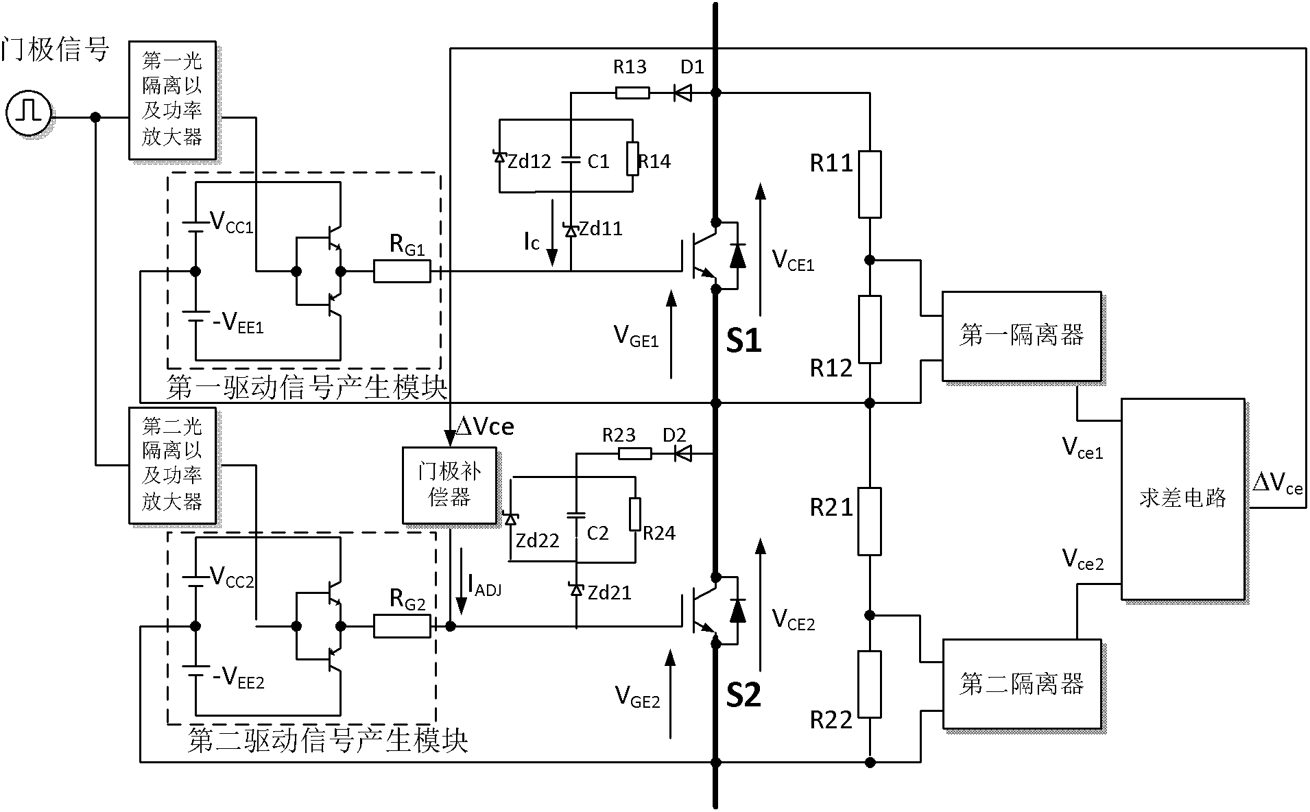
[0027] The voltage equalization control circuit of the insulated gate bipolar transistors in series operation proposed by the present invention, the circuit schematic diagram is as follows figure 1 shown, including:

[0028] The first optical isolation and power amplifier and the second optical isolation and power amplifier are respectively used to isolate and amplify the gate signal from the gate processor that controls the on-off of the insulated gate bipolar transistor to obtain an amplified gate Pole control signal;

[0029]The first driving signal generating module and the second driving signal generating module are respectively used to perform power modulation processing on the above-mentioned amplified gate control signal, and generate the first driving signal of the main IGBT transistor and the slave IGBT a second driving signal of the transistor;

[0030] Also includes: a master-slave control circuit and an active clamp control circuit, wherein the master-slave cont...


PUM


Abstract

The invention relates to a voltage sharing control circuit for the series operation of insulated gate bipolar transistors, and belongs to the technical field of electric automation equipment. The control circuit is provided with a master and slave control circuit and an active clamping control circuit. The master and slave control circuit realizes voltage sharing control over the insulated gate bipolar transistors by an isolation sampling module for voltages of insulated gate bipolar transistor devices, a difference comparison module and a controllable gate signal compensator. The active clamping control circuit consists of a first-level clamping voltage regulator tube, a second-level clamping voltage regulator tube, a charging and discharging capacitor, a first current limiting resistor and a first discharging resistor, and a DC bus injects current to the gates of the insulated gate bipolar transistors to realize a clamping state. The two circuits can perform voltage sharing regulation on the dynamic voltage sharing for the shunt-wound insulated gate bipolar transistors at the same time to achieve good control effects and relatively higher reliability, reduce loss in the voltage sharing of the insulated gate bipolar transistors and ensure the secure clamping of the voltages.

Description

technical field [0001] The invention relates to a voltage equalization control circuit for insulated gate bipolar transistors running in series, in particular to an insulated gate bipolar circuit suitable for high-voltage frequency converters or converters in high-voltage DC transmission systems. The invention relates to a transistor series voltage equal sharing control circuit, which belongs to the technical field of electrical automation equipment. Background technique [0002] Insulated gate bipolar transistor (Insolated Gate Bipolar Transistor, hereinafter referred to as IGBT) is a power electronic semiconductor device widely used in the field of electrical automation. Because it has the advantages of fast speed, high input impedance, small driving current, and simple driving circuit, as well as high withstand voltage, high current, and small on-state voltage drop, it develops rapidly, ranging from several kilowatts to several megawatts. Watts of power electronic equipm...

Claims


Application Information

Patent Timeline
Patent Type & Authority Applications(China)
IPC IPC(8): H02M1/00
Inventor 杨耕韩立博耿华王春风
Owner TSINGHUA UNIV
Learn More