steam prime mover

A technology of prime mover and steam, which is applied to steam engine devices, engine components, machines/engines, etc., to achieve the effect of suppressing thrust

Inactive Publication Date: 2011-12-21
KOBE STEEL LTD
View PDF7 Cites 0 Cited by
  • Summary
  • Abstract
  • Description
  • Claims
  • Application Information

AI Technical Summary

Problems solved by technology

Although the movement of the rotor to the air supply side can be prevented by modifying the bearing structure, etc., it is not preferable in terms of requiring a large modification of the steam turbine structure or in terms of weight, manufacturing cost, etc.

Method used


Image

  • steam prime mover
  • steam prime mover
  • steam prime mover

Examples


Embodiment Construction

[0040] Hereinafter, modes for implementing the present invention will be described with reference to the drawings. In the following description, the steam prime mover of the present invention is exemplified as a steam prime mover for driving a generator, but the steam prime mover of the present invention can also be used as a prime mover for driving equipment other than a generator such as a compressor. motivation.

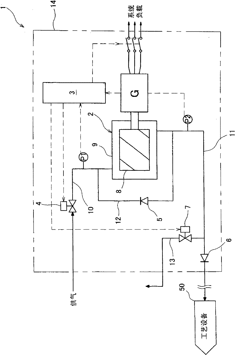
[0041] (Structure of a steam generator equipped with a steam prime mover)

[0042] Such as figure 1 As shown, the steam generator 1 mainly includes a positive displacement steam turbine 2 and a generator G connected to the positive displacement steam turbine 2 . The positive displacement steam turbine 2 and the generator G are accommodated in the unit cover 14 together with other auxiliary equipment (the control panel 3 and the like, details will be described later). Among the plurality of devices constituting the steam generator 1 , a group of devices other th...


PUM


Abstract

The present invention provides a steam power engine. The reverse direction thrust force produced at the time of emergency shut down can be suppressed, without performing significant reexamination of turbine structure. The engine comprises displacement type turbine rationally driven by a steam; a feed pipe and an exhaust pipe connected to the displacement type turbine; and an emergency quick closing valve attached to the feed pipe. The engine also comprises an exhaust gas return pipe branched between the emergency quick closing valve attached to the feed pipe, and the displacement turbine and connected to the feed pipe from the exhaust pipe; a first check valve attached to the return pipe; and a solenoid valve attached on a discharge pipe branched form the exhaust pipe. The first check valve is opened and a steam is returned to the feed pipe between the emergency closing valve and the displacement turbine when air supply lateral-pressure force is declined by the operation of the emergency closing valve.

Description

technical field [0001] The present invention relates to a steam prime mover for converting steam energy into mechanical energy (power). In particular, it relates to a steam prime mover equipped with a positive displacement steam turbine. Background technique [0002] As a general heating source, steam is widely and effectively used, but depending on the system, atmospheric release or condensation circulation may be performed as it is without heat utilization. Furthermore, when steam is used in various production processes, since the steam pressure is controlled by a pressure reducing valve, the pressure difference energy during decompression is not effectively utilized. In order to effectively utilize the unused steam energy, the present applicant has developed a steam generator that efficiently recovers steam energy as mechanical energy (power) to generate electricity. It should be noted that, in order to efficiently recover steam energy as mechanical energy (power), a di...

Claims


Application Information

Patent Timeline
Patent Type & Authority Applications(China)
IPC IPC(8): F01D17/10
CPCF01D15/10F01D17/08F01D21/00F01K13/02F05D2220/31
Inventor 桑原英明松井孝益松隈正树
Owner KOBE STEEL LTD
Why Eureka
Try Eureka