Two-stage centrifugal pump

A technology for centrifugal pumps and rotors, applied to pumps, pump devices, pump components, etc., which can solve the problems of reduced durability and achieve the effects of improved durability, increased discharge flow, and reduced wear

Active Publication Date: 2022-02-18
HITACHI ASTEMO LTD
View PDF18 Cites 0 Cited by
  • Summary
  • Abstract
  • Description
  • Claims
  • Application Information

AI Technical Summary

Problems solved by technology

If the thrust is too large, the sliding bearings that rotatably support the impeller via the rotor shaft will wear out and reduce durability.

Method used


Image

  • Two-stage centrifugal pump
  • Two-stage centrifugal pump
  • Two-stage centrifugal pump

Examples


Embodiment Construction

[0061] Embodiments of the present invention will be described below with reference to the drawings.

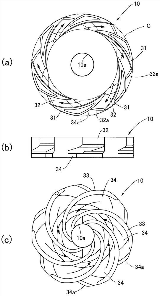
[0062] figure 1 is a longitudinal sectional view of a two-stage centrifugal pump of the present invention, figure 2 It is a figure which shows the guide vane member of this two-stage centrifugal pump, (a) is a top view, (b) is a side view, (c) is a bottom view.

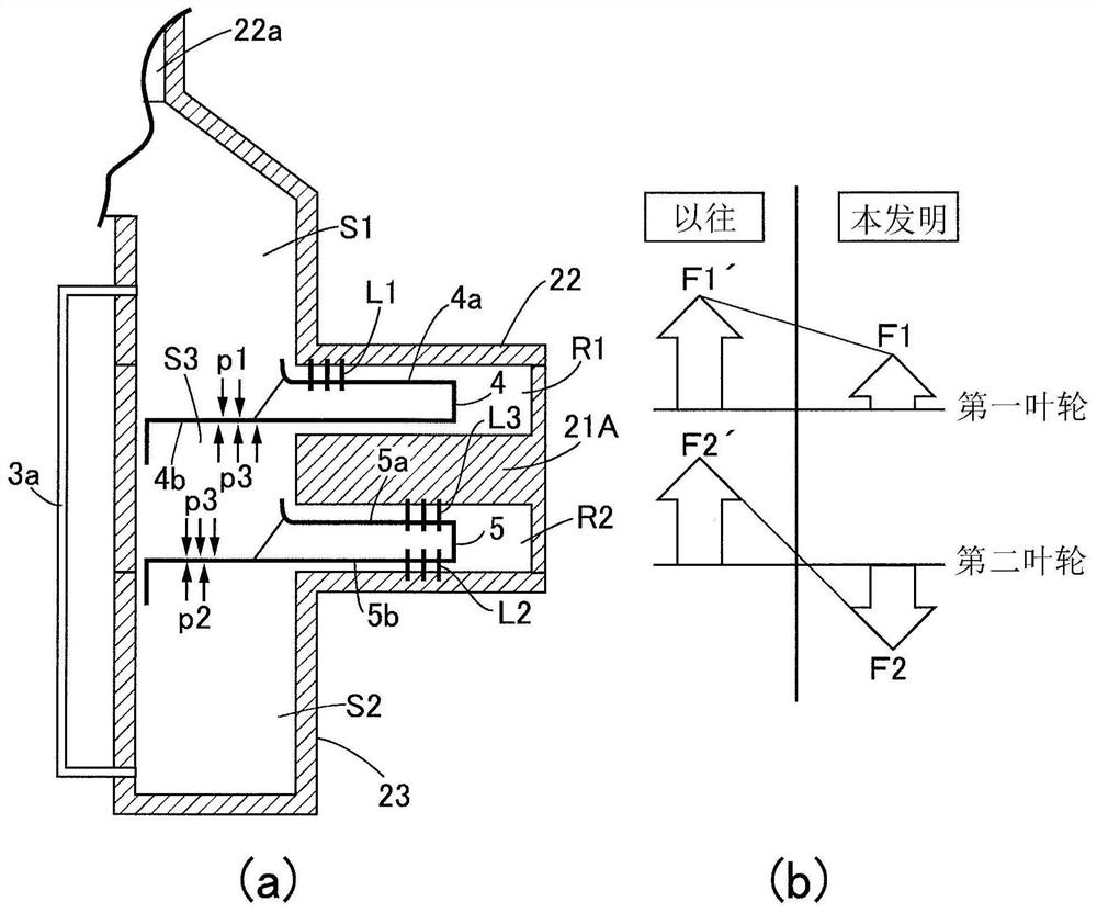
[0063] figure 1 The shown two-stage centrifugal pump 1 is a hermetic motor pump constructed to be figure 1 The pump part P arranged up and down (in the axial direction) and the motor part M as a drive source are connected along the same central axis to form an integral body, and a support shaft 6 is accommodated on the central axis and rotatably held on the support shaft 6 The hollow rotor shaft 3 is used to transmit the rotational power exerted by the motor part M to the pump part P, and sliding bearings 7 and 8 are interposed between the rotor shaft 3 and the support shaft 6 . In addition, the two-stage centrif...


PUM


Abstract

The invention provides a two-stage centrifugal pump, which does not cause the structure to be complicated or large, and can inhibit the thrust acting on a rotor shaft to be small, thereby improving the durability of a sliding bearing. The two-stage centrifugal pump (1) is configured such that two first and second impellers are axially mounted on a rotor shaft (3), the first impeller (4) and the second impeller (5) are respectively housed in two pump chambers (R1, R2) partitioned in a pump housing (2), and a first labyrinth seal (L1) is provided between a front surface shroud (4a) of the first impeller and an inner surface of the pump housing facing the front surface shroud (4a) of the first impeller, and a second labyrinth seal section (L2) is provided between a back shield (5b) of the second impeller and the inner surface of the pump housing facing the back shield (5b). The two-stage centrifugal pump is provided with a communication passage (3a). The communication passage is configured so that a first space (S1) closer to the axial center side than the first labyrinth seal part and a second space (S2) closer to the axial center side than the second labyrinth seal part are communicated with each other in the pump housing.

Description

technical field [0001] The invention relates to a two-stage centrifugal pump equipped with a thrust balance mechanism. Background technique [0002] In a two-stage centrifugal pump as one form of fluid machinery, there is a structure in which two impellers, namely, a first impeller and a second impeller, are installed in the axial direction on a rotor shaft rotationally driven by a driving source such as an electric motor. The first impeller and the second impeller are accommodated in two pump chambers in the body divided by a partition wall (for example, refer to Patent Document 1). [0003] However, in general, in a centrifugal pump, the pressure of the process fluid is low on the suction side of the impeller, that is, the axial front surface side, and the pressure of the process fluid is high on the discharge side of the impeller, that is, in the centrifugal direction. Therefore, it is known that a pressure difference (suction side<discharge side) always occurs during...

Claims


Application Information

Patent Timeline
Patent Type & Authority Applications(China)
IPC IPC(8): F04D1/06F04D13/06F04D29/08F04D29/22F04D29/42
CPCF04D1/06F04D13/06F04D29/086F04D29/2266F04D29/426
Inventor 仙石幸治
Owner HITACHI ASTEMO LTD
Why Eureka
Try Eureka