
A control valve for a hydraulic wellhead safety valve control system

A control system and safety valve technology, applied in wellbore/well valve devices, wellbore/well components, earth-moving drilling, etc., can solve the problems of oil and gas well production stagnation, affecting work efficiency, low safety performance, etc. The effect of reducing the requirements of machining accuracy, improving the stability of use, and avoiding the influence of control accuracy

Active Publication Date: 2011-12-21
重庆市正华钻采设备有限公司
View PDF7 Cites 3 Cited by
  • Summary
  • Abstract
  • Description
  • Claims
  • Application Information

AI Technical Summary

Problems solved by technology

[0003] The control circuit of the control valve used in this hydraulic wellhead safety valve control system is connected with multiple hydraulic components. These components may fail under long-term working conditions, which will cause the hydraulic wellhead safety valve control system to fail, resulting in oil and gas well production. Stagnation affects work efficiency; at the same time, the piston is affected by the compression and expansion of the closed gas in the right part of the inner cavity liquid cylinder during the working process, its control accuracy is low, and its safety performance is not high

Method used


Image

  • A control valve for a hydraulic wellhead safety valve control system
  • A control valve for a hydraulic wellhead safety valve control system
  • A control valve for a hydraulic wellhead safety valve control system

Examples


Embodiment Construction

[0019] The present invention will be further described below in conjunction with accompanying drawing.

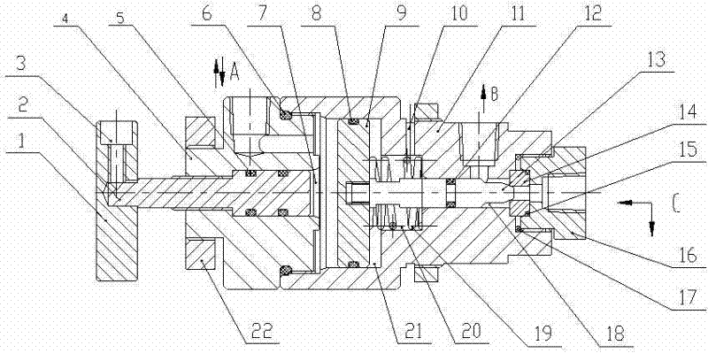
[0020] Such as figure 2 The control valve for the hydraulic wellhead safety valve control system shown includes a valve body 11, a valve hole 18 located in the center of the valve body 11, a valve core 13 located in the valve hole 18, and a front valve connected to one end of the valve body 11 by threads. Bonnet 16, the rear bonnet 4 that is threadedly connected to the other end of valve body 11; The valve core 13 and the valve hole 18 intermittent fit are provided with the fourth sealing ring 12, and the front bonnet 16 and the valve body 11 joint are provided with the first Five sealing rings 17, the second sealing ring 6 is provided at the connection between the rear valve cover 4 and the valve body 11; the inner cavity liquid cylinder 21 and the inner cavity liquid cylinder 21 are successively arranged in the valve body 11 at the end connected with the rear valve cover...


PUM


Abstract

The invention discloses a control valve for a hydraulic well mouth safety valve control system. The control valve comprises a valve body, a valve port formed in the center of the valve body, a valve plug positioned in the valve port, a front valve cover connected to one end of the valve body, and a rear valve cover connected to the other end of the valve body; an inner cavity hydraulic cylinder and a spring hole communicated with the inner cavity hydraulic cylinder are sequentially arranged in the valve body at one end connected to the rear valve cover; a piston connected with one end of the valve plug is matched in the inner cavity hydraulic cylinder, and separates the cavity hydraulic cylinder into a left part and a right part; a compression spring is matched in the spring hole, and is sleeved on the upper part of the valve plug; an oil inlet C is formed in the center of the front valve cover; an oil outlet B is formed on the side face of the valve body close to the front valve cover; the oil inlet C and the oil outlet B are communicated with the valve port; the center of the rear valve cover is provided with an inner hole partially communicated with the left part of the inner cavity hydraulic cylinder; a manual well opening screw is connected in the inner hole; and the side face of the rear valve cover is provided with a liquid communicating port A communicated with the left part of the inner cavity hydraulic cylinder. The control valve can be manually controlled when the control system fails.

Description

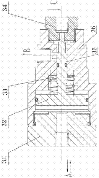
technical field [0001] The invention relates to a control valve for a hydraulic wellhead safety valve control system, which is used for controlling the normal input and discharge of high-pressure liquid oil in the hydraulic wellhead safety valve control system. Background technique [0002] The control valve of the existing hydraulic wellhead safety valve control system is completely controlled by hydraulic pressure, and once there is a problem in the control pipeline, the whole system will be in a state of paralysis. Such as figure 1 As shown in the existing control valve structure, when the hydraulic wellhead safety valve control system is in normal operation, the high-pressure liquid enters the left part of the inner cavity of the valve body 36 through the liquid flow hole A on the valve cover 31 after the control valve. Push the piston 32 to compress the spring 33, and at the same time compress the air in the right part of the inner cavity liquid cylinder until the tape...

Claims


Application Information

Patent Timeline
IPC IPC(8): E21B34/02
Inventor 周华安周郑华吴勇况忠明蒲仕钧朱方军蔡忠明
Owner 重庆市正华钻采设备有限公司
Learn More