
Energy-saving hydraulic shield propulsion system

A technology for shield tunneling and propulsion systems, which is applied in tunnels, mechanical equipment, fluid pressure actuation devices, etc., can solve the problems of high energy consumption, low overall hydraulic system efficiency, and large installed power.

Inactive Publication Date: 2011-12-14
BEIJING SANY HEAVY MASCH CO LTD
View PDF4 Cites 29 Cited by
  • Summary
  • Abstract
  • Description
  • Claims
  • Application Information

AI Technical Summary

Problems solved by technology

The propulsion system has a large installed power and high energy consumption. In order to reduce control costs and control complexity, a certain number of hydraulic cylinders distributed along the circumferential direction of the shield are usually partitioned, and proportional control valves are used to realize the compounding of pressure and flow in each zone. Control, due to the introduction of hydraulic valves such as proportional pressure valves and proportional speed control valves, energy losses such as overflow losses, throttling losses, and leakage losses will inevitably occur, resulting in low overall efficiency of the hydraulic system

Method used


Image

  • Energy-saving hydraulic shield propulsion system
  • Energy-saving hydraulic shield propulsion system

Examples


Embodiment Construction

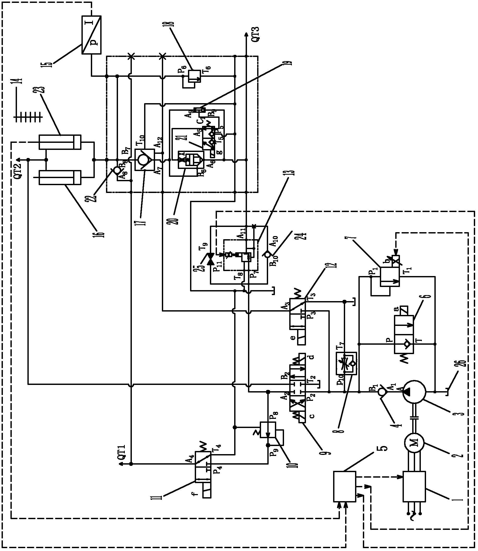
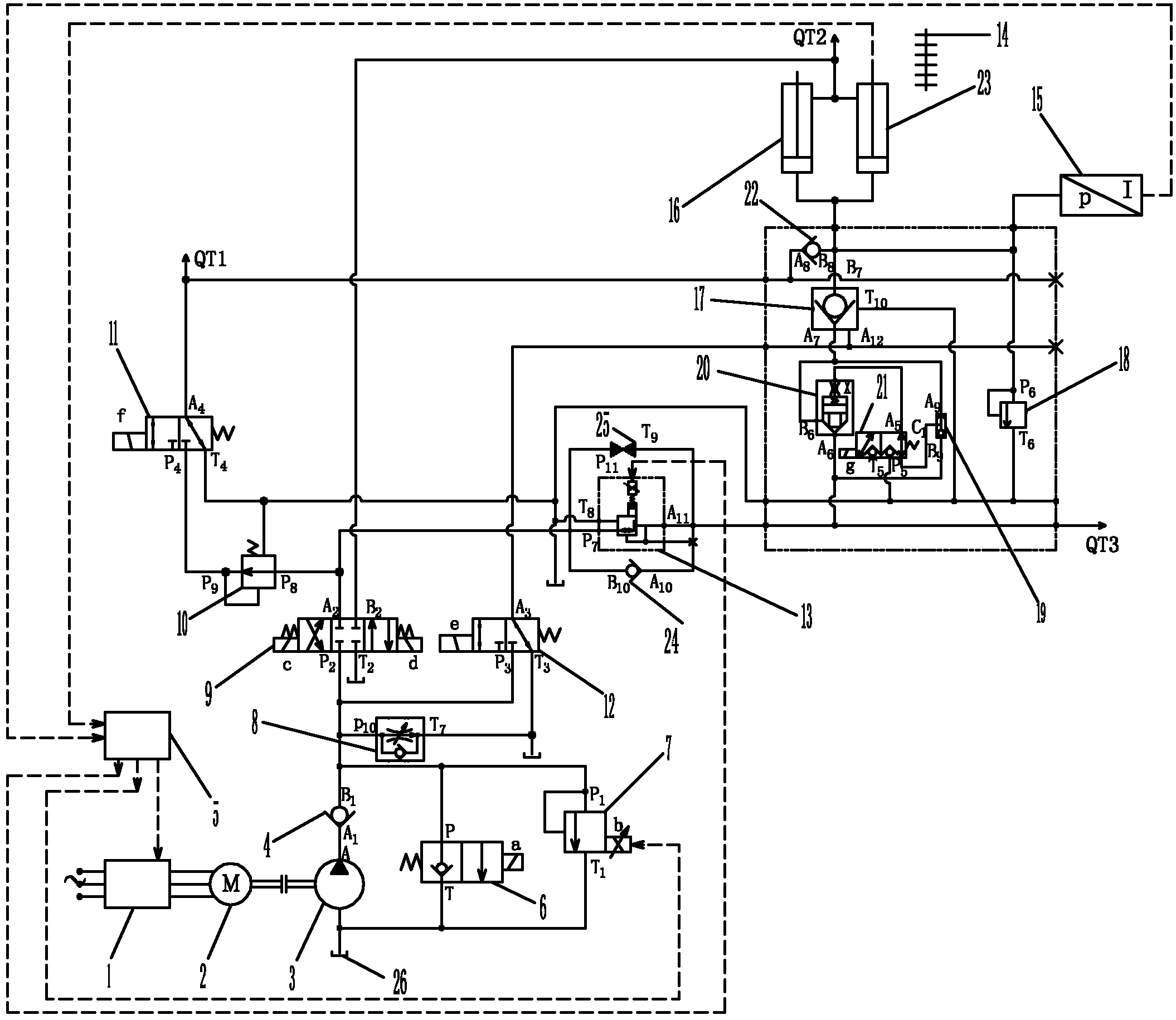
[0015] Such as figure 1 As shown, the present invention includes a controller 5, a frequency converter 1, a frequency conversion motor 2, a quantitative pump 3, an oil tank 26, a first one-way valve 4, a two-position two-way electromagnetic reversing valve 6, a proportional overflow valve 7, and a speed regulating valve. Valve 8, three-position four-way electromagnetic directional valve 9, differential pressure reducing valve 10, first two-position three-way electromagnetic directional valve 11, second two-position three-way electromagnetic directional valve 12, proportional pressure reducing valve 13, The third one-way valve 24, the ball valve 25, the cartridge valve 20, the third two-position three-way electromagnetic reversing valve 21, the shuttle valve 19, the safety valve 18, the hydraulic control one-way valve 17, the second one-way valve 22, the third A hydraulic cylinder 16 , a second hydraulic cylinder 23 , a pressure sensor 15 and a built-in displacement sensor 14 i...


PUM


Abstract

The invention relates to an energy-saving hydraulic shield propulsion system, and aims to provide a hydraulic shield propulsion system. The rotating speed of a variable frequency motor is controlled by adopting a frequency converter to regulate the output flow of a constant flow pump to make the output flow of a hydraulic pump matched with the required flow of the shield propulsion system, so that the aim of saving energy is fulfilled. The energy-saving hydraulic shield propulsion system comprises a controller, the frequency converter, the variable frequency motor, the constant flow pump, a proportional pressure reducing valve, electromagnetic valves, sensors and hydraulic cylinders. Detected signals are output to the controller by a pressure sensor and a built-in displacement sensor, and the frequency converter is controlled by the controller, and controls the rotating speed of the variable frequency motor to regulate the output flow of the constant flow pump to be matched with the required flow of the shield propulsion system without producing a redundant flow to maximally avoid energy loss and further realize energy saving.

Description

technical field [0001] The invention relates to tunnel excavation equipment, in particular to a propulsion hydraulic system for driving a shield machine. Background technique [0002] The full name of the shield machine is the shield tunnel boring machine. It is a modern high-tech excavation equipment dedicated to the construction of underground tunnels. It integrates machinery, electricity, hydraulics, control, and measurement technologies. , Segment assembly and other work have realized the mechanization and automation of tunnel excavation. Compared with the traditional tunnel construction method, the shield tunneling method has many advantages such as safe construction, fast and efficient construction, high engineering quality, small ground disturbance, high degree of mechanization, and low construction cost, especially when the geological conditions are complex, the groundwater level is high and the tunnel When the burial depth is large, only shield construction can be ...

Claims


Application Information

Patent Timeline
IPC IPC(8): E21D9/093F15B11/02
Inventor 董炳坤许汉中郭泗祥
Owner BEIJING SANY HEAVY MASCH CO LTD
Learn More