
Double-bionic tree-shaped pipe bundle type condenser of umbrella-shaped air cooling area

An air-cooled zone and condenser technology, which is applied to steam/steam condensers, lighting and heating equipment, etc., can solve the problems of affecting the performance of the condenser and the large air resistance of the evacuation pipeline, and achieves obvious energy saving effect and no air extraction. The effect of short reheat and large heat transfer coefficient

Active Publication Date: 2012-12-26
TSINGHUA UNIV
View PDF3 Cites 0 Cited by
  • Summary
  • Abstract
  • Description
  • Claims
  • Application Information

AI Technical Summary

Problems solved by technology

However, patent document 201010197078.9 (comparative document 1) also has some shortcomings in some cases, that is, the evacuation pipeline of this structure is usually connected to the vacuum equipment from the trumpet-shaped neck on the upper part of the condenser. On the one hand, its evacuation pipeline The length of the evacuated pipe is longer than that connected from the lower part of the condenser, so the air resistance generated by the evacuated pipe is relatively large. Heat also affects the performance of the condenser to a certain extent

Method used


Image

  • Double-bionic tree-shaped pipe bundle type condenser of umbrella-shaped air cooling area
  • Double-bionic tree-shaped pipe bundle type condenser of umbrella-shaped air cooling area
  • Double-bionic tree-shaped pipe bundle type condenser of umbrella-shaped air cooling area

Examples


Embodiment 1

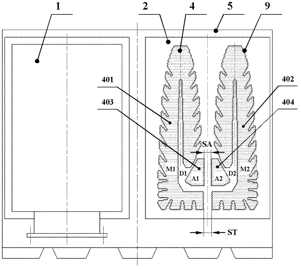
[0034] figure 1 It is a structural schematic diagram of a condenser according to an embodiment of the present invention. figure 2 It is a left view structural schematic diagram of the condenser of Embodiment 1 of the present invention, in figure 2 In , the right front water chamber is disassembled to show the arrangement of the heat exchange tubes of the condenser end tube plate. image 3 It is a schematic sectional view (half side) of the three-dimensional structure of the condenser of Embodiment 1 of the present invention.

[0035] exist figure 1 , figure 2 and image 3 Among them, condenser water chamber 1 is divided into front water chamber and rear water chamber, each with 2 pieces, condenser end tube plate 2 is divided into front end tube plate and rear end tube plate, each with 2 pieces, middle tube plate 3 It is arranged symmetrically on both sides, with 11 pieces on each side, the middle tube plate 3 has 2×11=22 pieces, and several heat exchange tubes 4 (in th...

Embodiment 2

[0047] Figure 9 It is a structural schematic diagram (half side) of the mid-section of the condenser of Embodiment 2 of the present invention. exist Figure 9 Among them, the tube bundle of the half-side condenser in this embodiment is a double bionic tree-shaped tube bundle of an umbrella-shaped air-cooling zone symmetrically arranged, and each bionic tree-shaped tube bundle (independent main cooling tube bundle unit) consists of 5575 heat exchange tubes Composition, each adjacent tapered air-cooled area tube bundle (independent air-cooled tube bundle unit) is composed of 391 heat exchange tubes, and the tube bundle arrangement of the half-side condenser in this embodiment has a total of 11932 heat exchange tubes. There are 23864 heat exchange tubes in the condenser.

[0048] exist Figure 9 Among them, the air-cooled steam baffle assembly 7 and the two tapered air-cooled zone tube bundles (A1 and A2) and the evacuation pipe 6 form an "umbrella" shape. The difference from...

Embodiment 3

[0052] Figure 10 It is a schematic diagram (half side) of the middle section structure of the condenser of embodiment three of the present invention, Figure 11 yes Figure 10 A schematic diagram of the local structure.

[0053] exist Figure 10 and Figure 11 Among them, the air-cooled steam baffle assembly 7, the air-cooled connecting pipe 12, the two tapered air-cooled zone tube bundles and the evacuation pipe 6 form an "umbrella" shape, wherein the upper steam baffle 701 and the air-cooled connecting pipe 12 are shaped like an "umbrella" The vertical steam baffle 702 and the evacuation pipeline 6 are shaped like a "vertical" in the middle of the word "umbrella". There is a certain gap between the two vertical steam baffles 702, and 703 is "umbrella". The Chinese-shaped horizontal steam plate is shaped like a "horizontal" in the middle of the word "umbrella". The upper space of " font communicates with the air-cooling connecting pipe. exist Figure 10 and Figure 1...


PUM


Abstract

The invention discloses a double-bionic tree-shaped pipe bundle type condenser of an umbrella-shaped air cooling area and belongs to the technical field of heat exchangers. The condenser consists of a plurality of heat exchange pipes, an end pipe plate, an intermediate pipe plate, an air cooling steam baffle component, an evacuation pipeline, a shell component, a water chamber and the like, wherein the heat exchange pipes on the end pipe plate of the condenser are in two separated bionic tree shapes to form a double-bionic tree-shaped pipe bundle; and the air cooling steam baffle component, two gradually-reduced air cooling pipe bundles, an air cooling communication hole or an air cooling communication pipe and the evacuation pipeline form an umbrella-shaped air cooling pipe bundle component. The condenser has the advantages of uniform and vortex-free steam flow field of the bundles of the condenser, low steam resistance, uniform heat load, low degree of super-cooling, reheat-free airevacuation, shorter evacuation pipe and higher heat transfer coefficient of the condenser. The heat transfer coefficient of the condenser can be higher than a calculation value according to a heat exchange institute (HEI) standard by over 10 percent. The condenser is obvious in energy-saving effect of a condenser set.

Description

technical field [0001] The invention belongs to the technical field of large-scale power station heat exchangers, in particular to a double-bionic tree-shaped tube-bundle condenser in an umbrella-shaped air-cooling zone, in particular to the arrangement of tube bundles in the air-cooling zone of the cooling tube bundle in the water-cooled condenser of a large-scale power station It is an umbrella-shaped air-cooling zone double-bionic tree-shaped tube-bundle condenser in the shape of an "umbrella" and the main cooling tube bundle is arranged in two bionic tree structures. Background technique [0002] The power plant condenser is an important component of thermal power generation and nuclear power units. Its function is to condense the exhaust steam discharged from the steam turbine into water and establish and maintain a certain vacuum at the steam exhaust port of the steam turbine. The rationality of the cooling tube bundle layout of the water-cooled condenser in a large po...

Claims


Application Information

Patent Timeline
Patent Type & Authority Patents(China)
IPC IPC(8): F28B1/06
Inventor 孟继安
Owner TSINGHUA UNIV
Learn More