
Gas turbine cooling blade with crown

A technology for gas turbines and cooling blades, which is applied to the supporting elements of blades, engine elements, machines/engines, etc., can solve the problem of low cooling efficiency of cold air, achieve good processability and engineering application prospects, improve cooling effect, and simple structure Effect

Inactive Publication Date: 2011-07-20
NORTHWESTERN POLYTECHNICAL UNIV
View PDF11 Cites 24 Cited by
  • Summary
  • Abstract
  • Description
  • Claims
  • Application Information

AI Technical Summary

Problems solved by technology

[0003] In order to overcome the shortcomings of the prior art shrouded turbine cooling blades with low cooling efficiency per unit cold air, the present invention provides a gas turbine shrouded cooling blade, which has a relatively simple structure and can increase the cooling efficiency without increasing the amount of cooling air. The cooling efficiency of the blade body of the crown blade can effectively reduce the temperature of the blade body and the blade crown

Method used


Image

  • Gas turbine cooling blade with crown
  • Gas turbine cooling blade with crown
  • Gas turbine cooling blade with crown

Examples


Embodiment Construction

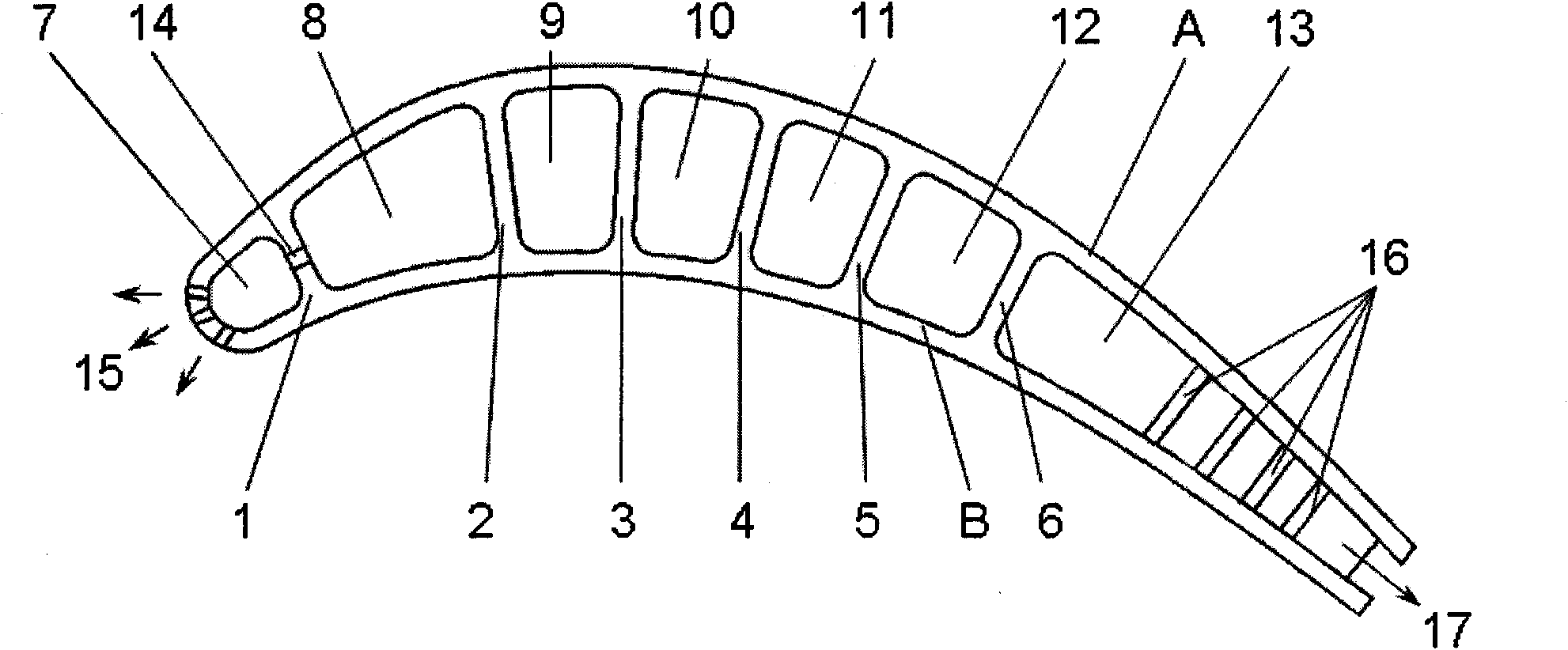
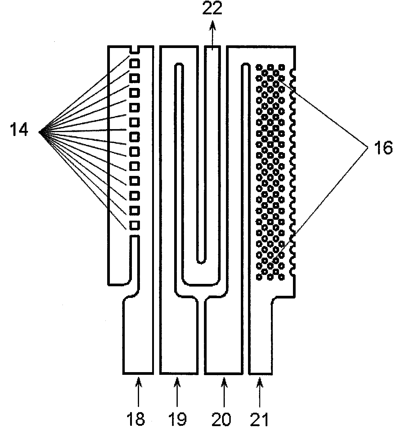
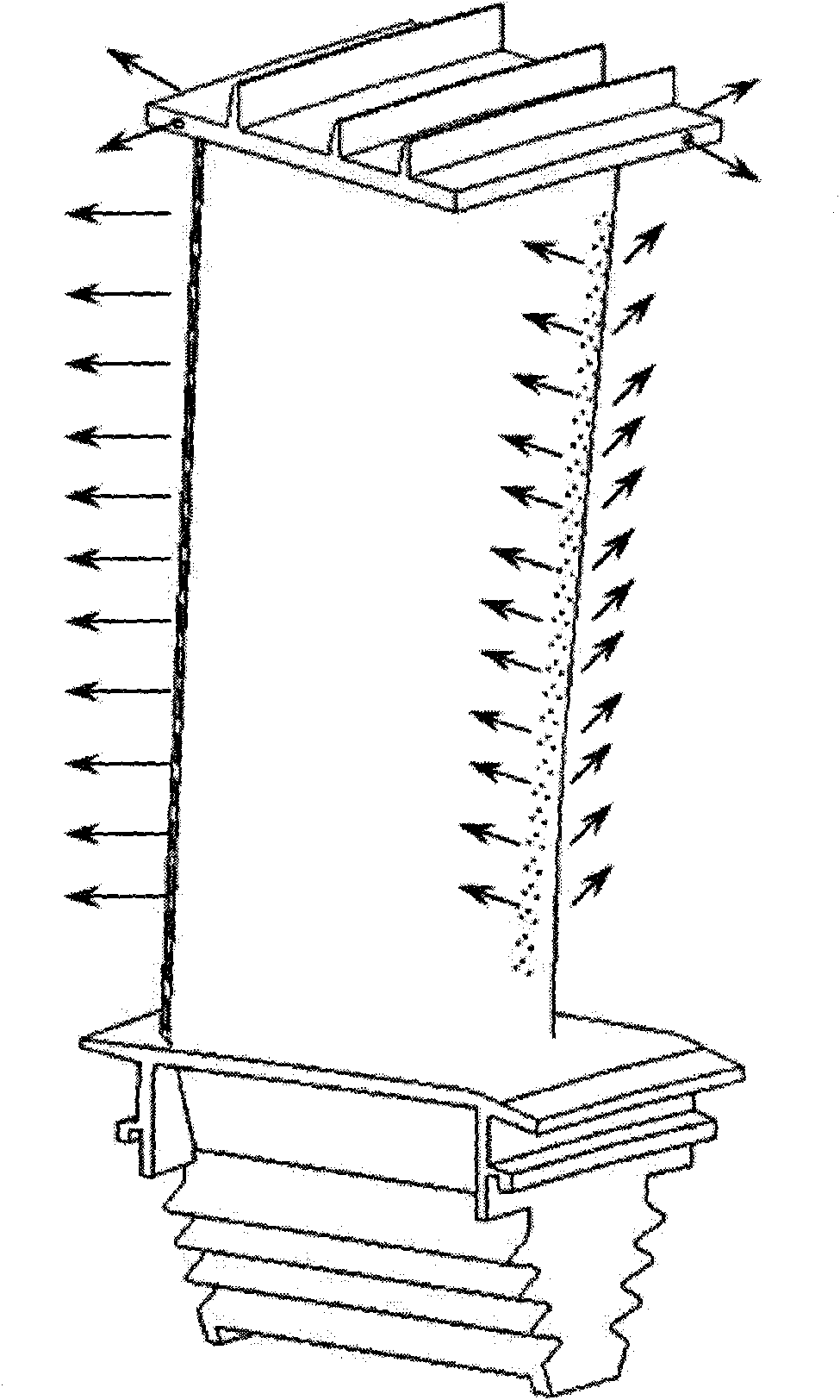
[0017] Such as figure 1 and figure 2 As shown, the airfoil of the crowned cooling blade includes an outer wall A and an inner wall B, and the partitions 1, 2, 2, 3, 4, and 5 are arranged in sequence from the leading edge to the trailing edge of the blade. 5. Partition plate six 6 divides the inner cavity of the blade into cooling chamber one 7, cooling chamber two 8, cooling chamber three 9, cooling chamber four 10, cooling chamber five 11, cooling chamber six 12 and cooling chamber seven 13, among which Plate two 2 and clapboard five 5 divide the cooling channel of the cooling blade airfoil into two independent parts: front, middle and rear; clapboard one 1 is equidistantly arranged with 12 impingement cooling holes 14, and the cooling air flows in the airfoil cooling cavity. When 28 is flowing, the cooling air is sprayed out through the impact cooling hole to blow the cooling air to the front edge of the inner wall B of the airfoil for cooling. There are air film holes 15...


PUM


Abstract

The invention discloses a gas turbine cooling blade with a crown. A plurality of clapboards which are arranged along the radial direction respectively are arranged from the leading edge of a blade body to the tail edge on the inner wall of the blade body; the inner cavity of the blade body is divided into three return flow type cooling channels which are formed along the longitudinal direction of the blade body; a clapboard at the headmost end is provided with impingement cooling holes, and the leading edge of the blade body is provided with air film holes; the tail end of a cooling channel on the middle part of the blade body is connected with a blade crown cooling cavity; partition ribs and turbulent flow posts are arranged and air vent holes are formed in the blade crown cooling cavity; an air vent seam is formed at the tail edge of the blade; and the turbulent flow posts are arranged in the air vent seam. The blade has a simple structure; and by the blade, the cooling efficiency is improved, the temperatures of the blade body and the blade crown are reduced, the loss of air leakage of a blade tip is reduced, and the properties of the turbine blade and the complete machine are improved.

Description

technical field [0001] The invention relates to a turbine cooling blade, which is especially suitable for aeroengines and gas turbines. Background technique [0002] Turbine blade is one of the key components in aviation gas turbine power plant, its function is to convert gas heat energy into turbomechanical work, therefore, the quality of turbine blade design is directly related to the performance of gas turbine and even the whole engine. Since gas turbine blades work in an extreme environment of high temperature, high pressure and high speed, the thermal stress, mechanical stress and ambient temperature related to this environment will significantly reduce the service life of the turbine blades. How to effectively cool the turbine blades and ensure that the blades Normal, reliable and long-term work is particularly important. Turbine cooling blade technology can effectively reduce the temperature of turbine blades and ensure the service life of turbine blades and their co...

Claims


Application Information

Patent Timeline
Patent Type & Authority Applications(China)
IPC IPC(8): F01D5/18
Inventor 温志勋李元生敖良波周国财杜鹏飞李磊于明岳珠峰
Owner NORTHWESTERN POLYTECHNICAL UNIV
Learn More