
Control system and control method for frostless refrigerator heater

A control system and defrosting heater technology, applied in lighting and heating equipment, household refrigeration equipment, household appliances, etc., can solve the problems of high cost, difficult verification of single-chip software, long time, etc., and achieve the effect of avoiding high temperature

Inactive Publication Date: 2013-03-20
HISENSE RONGSHENG YANGZHOU REFRIGERATOR CO LTD
View PDF0 Cites 0 Cited by
  • Summary
  • Abstract
  • Description
  • Claims
  • Application Information

AI Technical Summary

Problems solved by technology

[0006] Due to the invisible and difficult-to-verify features of single-chip software, it takes a long time and a high cost to pass the software safety evaluation certification. If the software safety evaluation certification cannot be obtained, additional safety measures need to be taken to ensure the safety of the defrosting heating system. safety

Method used


Image

  • Control system and control method for frostless refrigerator heater
  • Control system and control method for frostless refrigerator heater
  • Control system and control method for frostless refrigerator heater

Examples


Embodiment 1

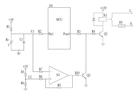
[0027] See attached figure 1 , in the input sampling circuit, the defrost temperature sensor RV is connected to the ground terminal. At this time, if the temperature rises, the resistance of RV becomes smaller, and the voltage at U1 decreases at this time. When the temperature of RV is higher than a certain limit temperature value T1 At this time, the voltage of U1 is lower than the U2 voltage value generated by the voltage division of R5 and R6, the operational amplifier N1 outputs a high level, and the transistor Q2 is turned on. At this time, even if the Pout1 port of the microcontroller outputs a high level, the transistor Q1 will also maintain cut off, the contact of relay K1 is disconnected, and the defrosting heater H1 is de-energized.

[0028] The range of T1 can be set to 10~50℃, and the voltage value of U2 can be changed by changing the resistance value of R5 or R6, so as to achieve the purpose of changing the limited temperature value T1.

Embodiment 2

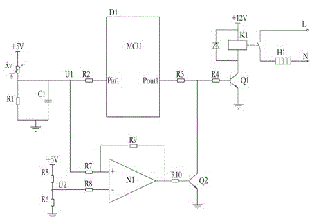
[0030] See attached figure 2 , In the input sampling circuit, the defrosting temperature sensor RV is connected to the +5V terminal. At this time, if the temperature rises, the resistance of RV becomes smaller, and the voltage at U1 increases at this time. When the temperature of RV is higher than a certain limit temperature value At T1, the voltage of U1 is higher than the U2 voltage value generated by the voltage division of R5 and R6, the operational amplifier N1 outputs a high level, and makes the transistor Q2 conduct. At this time, even if the Pout1 port of the microcontroller outputs a high level, the transistor Q1 will also be Keep off, the contact of relay K1 is disconnected, and the defrosting heater H1 is de-energized.

[0031] The range of T1 can be set to 10~50℃, and the voltage value of U2 can be changed by changing the resistance value of R5 or R6, so as to achieve the purpose of changing the limited temperature value T1.

[0032] The present invention realize...


PUM


Abstract

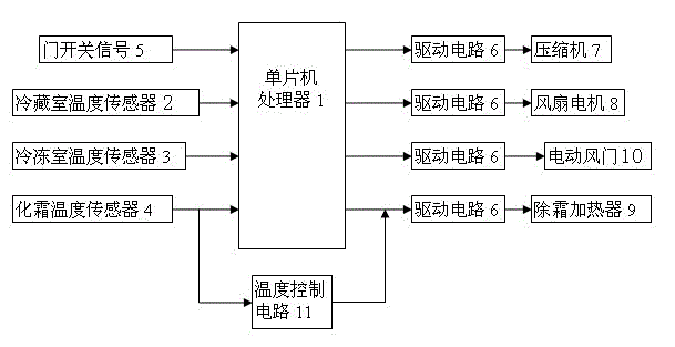
The invention relates to a control system and control method for a frostless refrigerator heater. The control system for the frostless refrigerator heater comprises a singlechip processor, as well as a refrigerating chamber temperature sensor, a freezing chamber temperature sensor, a defrosting temperature sensor and a door switching signal which are respectively connected with the singlechip processor, wherein the singlechip processor is respectively connected with a compressor, a fan motor, a defrosting heater and an electric air door through driving circuits; the control system also comprises a temperature control circuit which is connected between the driving circuits of the defrosting temperature sensor and the defrosting heater. According to the invention, by additional arrangement of the temperature control circuit, the function of controlling the defrosting heater by hardware circuits can be achieved, namely, no matter what status the single chip processor is in, the defrosting heater can be forced to power off when the temperature of the defrosting temperature sensor RV is too high, thus the safety performance of the product can be improved and the requirement of the safety standard can be satisfied.

Description

technical field [0001] The invention belongs to the technical field of electrical equipment, and in particular relates to a control system and a control method for a frost-free refrigerator heater. Background technique [0002] The evaporator of the refrigerator will accumulate frost on the surface after cooling for a period of time. If the frost layer is too thick, the heat exchange will deteriorate and the cooling performance will deteriorate. Therefore, the frost accumulation on the surface of the evaporator should be removed to ensure the performance of the refrigerator. The advantage of a frost-free refrigerator is that it can defrost automatically, and does not require the user to remove the frost accumulated on the surface of the evaporator. The control system of the frost-free refrigerator includes an automatic frosting process. During the defrosting process, the defrosting heater is energized and heated to remove the frost on the evaporator. [0003] Most of the cu...

Claims


Application Information

Patent Timeline
Patent Type & Authority Patents(China)
IPC IPC(8): F25D29/00
Inventor 陈星
Owner HISENSE RONGSHENG YANGZHOU REFRIGERATOR CO LTD
Learn More