
Cooling system and method for low-temperature liquid hydrocarbon storage tank

A low-temperature liquid, cooling system technology, applied in container discharge method, container filling method, gas/liquid distribution and storage, etc., can solve the problem of reducing low-temperature liquid hydrocarbon input speed, uneven cooling speed, and low-temperature liquid hydrocarbon storage tank cooling long time issues

Inactive Publication Date: 2011-11-30
CHINA HUANQIU CONTRACTING & ENG CO LTD
View PDF5 Cites 15 Cited by
  • Summary
  • Abstract
  • Description
  • Claims
  • Application Information

AI Technical Summary

Problems solved by technology

The above two problems will cause the cooling rate of each point inside the inner tank to be uneven. To keep the cooling rate of the inner tank within 3°C / hour, and the temperature difference between any two points does not exceed 30°C, it is necessary to reduce the low temperature as much as possible. The input velocity of liquid hydrocarbons, which results in very long cooling times for cryogenic liquid hydrocarbon storage tanks

Method used


Image

  • Cooling system and method for low-temperature liquid hydrocarbon storage tank
  • Cooling system and method for low-temperature liquid hydrocarbon storage tank
  • Cooling system and method for low-temperature liquid hydrocarbon storage tank

Examples


Embodiment Construction

[0066] The principles and features of the present invention are described below in conjunction with the accompanying drawings, and the examples given are only used to explain the present invention, and are not intended to limit the scope of the present invention.

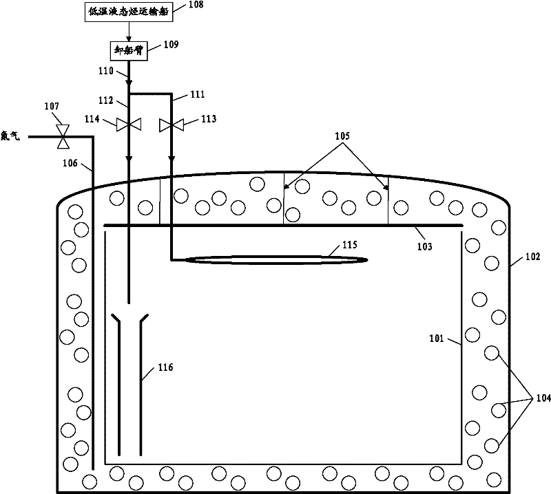
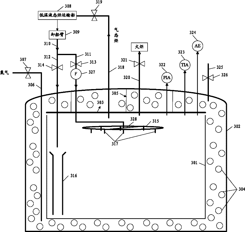
[0067] image 3 The structure diagram of the cryogenic liquid hydrocarbon storage tank and its cooling system provided by the present invention. Such as figure 1 As shown, the cryogenic liquid hydrocarbon storage tank in the present invention includes: an outer tank 302 and an inner tank 301 located inside the outer tank 302; the ceiling 303 of the inner tank 301 is connected with the vault of the outer tank 302 through a suspender 305; the outer tank 302 Insulation material 304 is filled between the inner surface of the inner tank 301 and the outer surface of the inner tank 301; the nitrogen purge pipe 306 passes through the vault of the outer tank 302 and enters the space between the outer tank 302 inside and the...


PUM


Abstract

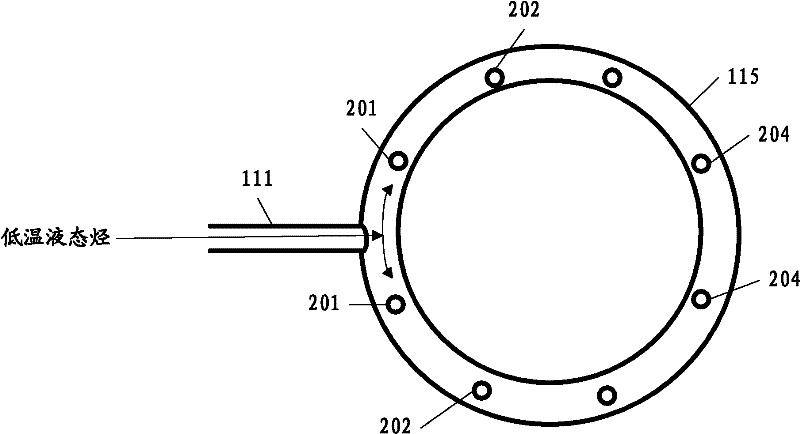
The invention relates to a cooling system and method for a low-temperature liquid hydrocarbon storage tank. The cooling system comprises a liquid hydrocarbon transportation ship, a ship unloading arm, a liquid hydrocarbon output general pipe, a cooling straight pipe and a cooling annular pipe, wherein the liquid hydrocarbon transportation ship carries liquid hydrocarbon; the ship unloading arm is connected with a liquid hydrocarbon output pipe of the liquid hydrocarbon transportation ship; the liquid hydrocarbon output general pipe is connected with an output end of the ship unloading arm to output the liquid hydrocarbon; the cooling straight pipe is connected with the liquid hydrocarbon output general pipe and enters the inside of an inner tank via an arc crown of an outer tank, an insulation material and a suspended ceiling of the inner tank sequentially; the cooling annular pipe is positioned in a horizontal plane in the inner tank, and comprises an edge annular pipe and a liquid hydrocarbon dispersion pipe, wherein the liquid hydrocarbon dispersion pipe penetrates the central point of the edge annular pipe and is used for dispersing liquid hydrocarbon; the edge annular pipe is communicated with the liquid hydrocarbon dispersion pipe, and the liquid hydrocarbon dispersion pipe is communicated with the cooling straight pipe at the central point of the edge annular pipe; and openings are uniformly distributed at the lower part of the edge annular pipe at intervals, and each opening is connected with a hollow nozzle used for spraying and atomizing outflowing liquid hydrocarbon. The cooling system and method provided by the invention enables the cooling speed of the storage tank to be uniform.

Description

technical field [0001] The invention relates to the field of low-temperature liquid hydrocarbon storage and transportation, in particular to a cooling system and a cooling method for a low-temperature liquid hydrocarbon storage tank. Background technique [0002] Low-temperature liquid hydrocarbons often refer to hydrocarbons with low boiling points at standard atmospheric pressure. They can only be turned into liquids under pressurized and cooled conditions. After liquefaction, their volume is reduced by hundreds of times, so they are very conducive to long-distance transportation. It includes liquefied natural gas (LNG), liquefied ethylene gas (LEG), liquid ethane, liquid propylene, propane, and the like. [0003] Due to the huge demand for low-temperature liquid hydrocarbons in my country at present, the domestic production of low-temperature liquid hydrocarbons can no longer meet the demand, so a large amount of imports is required. Such as figure 1 As shown, in the pr...

Claims


Application Information

Patent Timeline
IPC IPC(8): F17C13/00
Inventor 宋媛玲白改玲赵月峰安小霞王红李婵
Owner CHINA HUANQIU CONTRACTING & ENG CO LTD
Learn More