Heat radiation apparatus and manufacture method thereof

A technology of heat dissipation device and manufacturing method, which is applied in the direction of cooling/ventilation/heating transformation, etc., which can solve the problems of low heat transfer and heat dissipation efficiency, long working hours, small heat dissipation space, etc., and achieve the effect of rapid and convenient assembly

Inactive Publication Date: 2011-11-23
ASIA VITAL COMPONENTS SHENZHEN CO LTD
View PDF4 Cites 4 Cited by
  • Summary
  • Abstract
  • Description
  • Claims
  • Application Information

AI Technical Summary

Problems solved by technology

[0006] When heat sink components are combined with heat sink components, there will be gaps, so thermal resistance will occur. Therefore, it can be reduced by soldering. However, the combination of too many heat sink components is relatively poor in heat dissipation efficiency, and when passing through multiple Combining the combination of heat dissipation components to conduct heat together, the heat dissipation components need to go through the assembly process, which will take a long time and increase the cost
[0007] Furthermore, the combination of the base and the heat sink will increase the size of the heat sink itself, and it is inconvenient to carry and move relatively cumbersome, and it cannot be used in places where the heat dissipation space is limited because of its large volume; so the prior art has the following shortcoming:
[0008] 1. High cost;
[0009] 2. Consuming assembly man-hours;
[0010] 3. Not suitable for places with small cooling space;

Method used


Image

  • Heat radiation apparatus and manufacture method thereof
  • Heat radiation apparatus and manufacture method thereof
  • Heat radiation apparatus and manufacture method thereof

Examples


Embodiment Construction

[0044] The above-mentioned purpose of the present invention and its structural and functional characteristics will be described according to the preferred embodiments of the accompanying drawings.

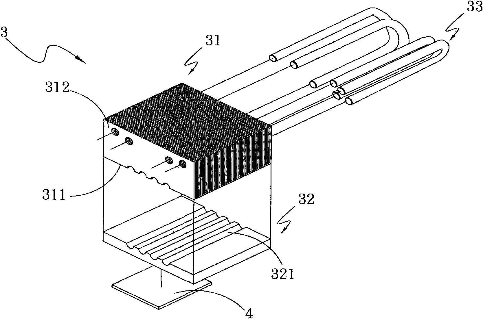
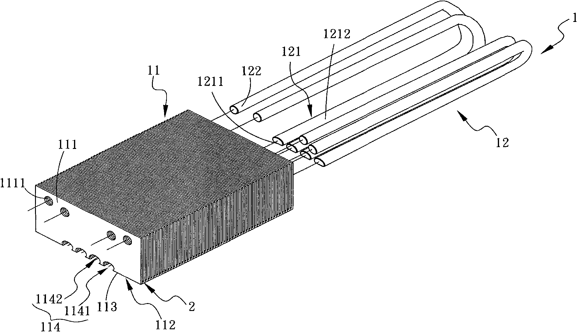
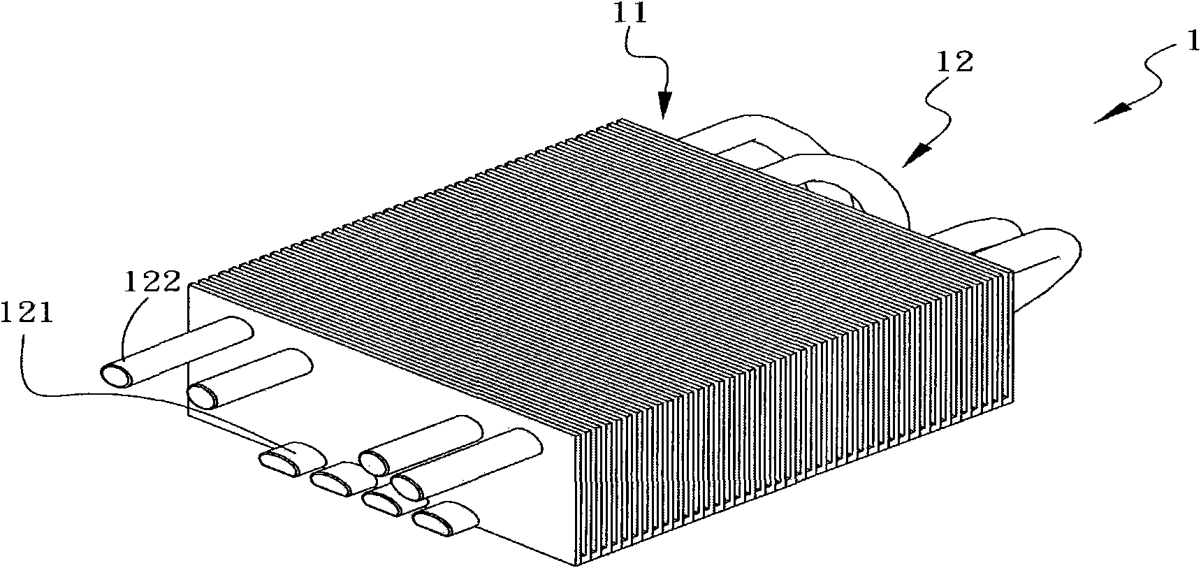
[0045] Please refer to Figures 2, 3, and 4, which are three-dimensional exploded and assembled views and front views of the first embodiment of the heat sink of the present invention. As shown in the figure, the heat sink 1 includes: a radiator 11, at least one heat pipe 12;

[0046] The heat sink 11 has a heat dissipation portion 111 and a heat absorption portion 112, the heat absorption portion 112 has an end surface 113, and the end surface 113 is concavely provided with at least one groove 114, and the groove 114 has an opening 1141 and a closed side 1142, the heat dissipation portion 111 is connected to the heat absorption portion 112, and is configured by extending one side of the heat absorption portion 112 to the opposite direction of the heat absorption portion 112, and th...


PUM


Abstract

The invention provides a heat radiation apparatus and a manufacture method thereof. The heat radiation apparatus comprises a radiator and at least a heat pipe, the radiator has a heat radiation part and a heat absorption part, the heat absorption part has an end face which is provided with at least a groove, and the groove has an opening and an enclosing side; the heat pipe has a heat absorption end and a heat radiation end, the heat absorption end has a heat absorption surface and a heat conduction surface, the heat absorption surface is close to the heat conduction surface, the heat absorption end of the heat pipe is embedded in the groove correspondingly, the heat conduction surface fits the enclosing end correspondingly, the heat absorption surface is aligned with the end face, and the heat radiation end of the heat pipe passes through the heat radiation part of the radiator; through the heat pipe at least one side is prepared as a flat surface, one side of heat radiation fins is provided with at least one groove and the heat radiation fins can be stacked mutually to form a radiator, the heat pipe goes through concave holes correspondingly to form a heat radiation apparatus, or the heat radiation fins go into the heat pipe to form a heat radiation apparatus. In this way, thermal resistance is reduced, cost and weight is reduced, and a good heat radiation effect is realized.

Description

technical field [0001] The invention relates to a heat dissipation device and a manufacturing method thereof, in particular to a heat dissipation device capable of saving manufacturing cost and reducing thermal resistance and a manufacturing method thereof. Background technique [0002] Heat pipes are currently a heat transfer component widely used in electronic equipment and electronic components. Generally speaking, heat pipes are filled with heat transfer media with good fluidity, high heat of vaporization, low boiling point and stable chemical properties, such as water, ethanol, etc. and acetone, etc., and the inner wall surface of the heat pipe is usually formed with a capillary structure with many burr-like protrusions. [0003] In actual use, one end of the heat pipe is used as an evaporating section and connected to a heat pipe seat installed on an electronic component, while the other end of the heat pipe is used as a condensing section, which can be installed on mo...

Claims


Application Information

Patent Timeline
IPC IPC(8): H05K7/20B23P15/26
Inventor 林国胜孙立旻郑清祥
Owner ASIA VITAL COMPONENTS SHENZHEN CO LTD
Why Eureka
Try Eureka