Eureka AIR delivers breakthrough ideas for toughest innovation challenges, trusted by R&D personnel around the world.

Heat insulating structural system suitable for existing building masonry and construction method thereof

A technology of existing buildings and construction methods, applied in the direction of building structure, building components, and building materials, can solve problems such as poor fire performance, poor heat preservation, poor heat insulation performance, and complicated construction process, and achieve a good society Benefits and economic benefits, ensuring safety and durability, and reducing construction waste

Inactive Publication Date: 2011-11-23
河南省九建工程有限公司 +1
View PDF5 Cites 4 Cited by
  • Summary
  • Abstract
  • Description
  • Claims
  • Application Information

AI Technical Summary

Problems solved by technology

This heat preservation and energy-saving transformation process of the existing wall is complicated and slow, and the wall is easy to crack and hollow.
Poor heat preservation and heat insulation performance, poor fire performance, high cost, long construction period, cannot guarantee the safety of pasted bricks, and the service life of this type of external wall insulation structure is short (25 years), and it will appear after more than 20 years Quality problems and maintenance costs, and the service life of buildings is generally 50 to 70 years, so the life of the wall and the house will not be synchronized, and quality problems such as cracking and peeling of the outer surface of the building often occur within the design service life , does not have a good thermal insulation effect and affects the appearance. During the repair process, a large amount of construction waste will be generated, polluting the environment

Method used


Image

  • Heat insulating structural system suitable for existing building masonry and construction method thereof
  • Heat insulating structural system suitable for existing building masonry and construction method thereof

Examples


Embodiment 1

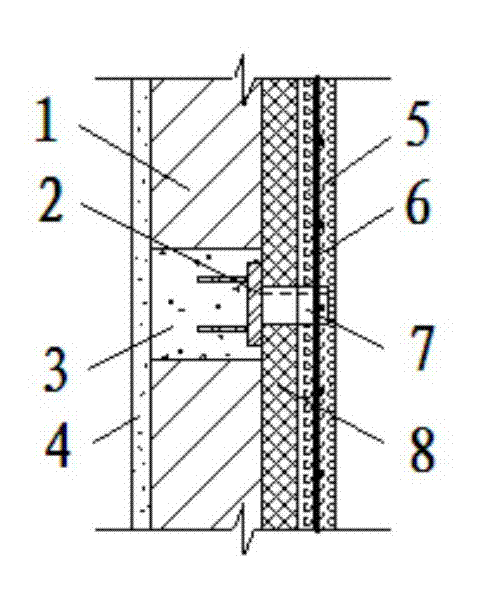
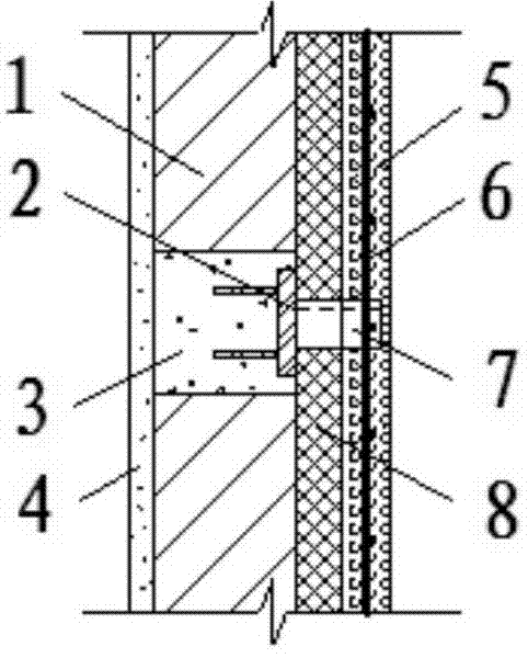
[0029] Example 1 A thermal insulation structural system suitable for existing building masonry, see figure 1 , from the inside to the outside, including the inner decorative layer 4, the existing foundation wall layer 1, the thermal insulation layer (XPS insulation board) 8, the concrete protective layer (thickness 50mm) 5, its strength is not lower than C25, the thermal insulation layer 8 is fixed between the existing foundation wall layer 1 and the concrete protective layer 5, and is provided with concrete anchors 3 at certain distances along the vertical and horizontal directions of the existing foundation wall layer 1, and the concrete anchors 3 are embedded with The embedded part 2 is provided with a reinforcing steel bar 6 in the concrete protective layer 5 , and the reinforcing steel bar 6 is anchored to the embedded part 2 through a tension member 7 penetrating the thermal insulation layer 8 .

[0030] The thickness of the XPS insulation board is set according to the l...


PUM


Abstract

The invention relates to a heat insulating structural system suitable for an existing building masonry and a construction method thereof. The system comprises an inner decorative layer, an existing foundation wall layer, a heat insulating layer and a concrete protection layer from inside to outside; concrete anchors for anchoring embedded parts are arranged in the existing foundation wall layer at intervals; reinforcing steel bars are arranged in the concrete protection layer; and the reinforcing steel bars are anchored with the embedded parts through pulling connectors passing through the heat insulating layer. The system has long service life and good fireproof performance, and can ensure sticking safety and durability of face bricks; and a dispersed pulling bridge connecting mode is adopted between the existing foundation wall and the concrete protection layer, so that the layers are connected tightly, safely and reliably, the heat bridge effects of the pulling bridges of the inner and outer layers are dispersed, heat transfer of a building envelope is balanced, the heat transfer coefficient of each part is controlled close, uniform heat transfer of each part is ensured, and the influence of the connected heat bridges on the heat insulating effect is reduced.

Description

technical field [0001] The invention relates to the field of engineering construction, in particular to a thermal insulation structure system suitable for existing building masonry and a construction method thereof. Background technique [0002] The energy consumption of existing buildings in my country, especially those built before 2000, is about 2 to 3 times that of new buildings. The living environment is poor and the stock is huge. According to statistics, by the end of 2000, the number of residential buildings in need of energy-saving renovation in the northern heating area alone reached 3.168 billion m2 2 . Therefore, with the development of my country's economy and the reality that the total number of new buildings will continue to grow, the energy-saving renovation of existing buildings will be of great significance to the achievement of China's energy-saving and emission-reduction goals. The wall occupies the largest volume of the envelope. The heat lost through...

Claims


Application Information

Patent Timeline
Patent Type & Authority Applications(China)
IPC IPC(8): E04B1/76E04B1/80E04G21/14
Inventor 胡保刚朱军李群虎胡伦坚周倩闫长国秦明宇刘新立张晋徐桂灵杨超
Owner 河南省九建工程有限公司
Why Eureka
Eureka Blog
Learn More