Ultrasonic diagnostic device, ultrasonic image processing device, and medical image diagnostic device
A technology of image processing device and diagnostic device, which is applied in the directions of acoustic wave diagnosis, ultrasonic/sonic wave/infrasonic wave diagnosis, infrasonic wave diagnosis, etc., to achieve the effect of simple visual recognition
- Summary
- Abstract
- Description
- Claims
- Application Information
AI Technical Summary
Problems solved by technology
Method used
Image
Examples
Deformed example 1
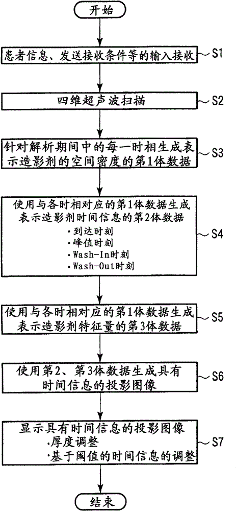
[0111] In the present four-dimensional parametric imaging, in the projection processing of step S6, the thickness (projection range) of data in the depth direction to be the object of the projection processing can be adjusted. For example, a desired tomographic image is displayed according to a user's instruction. The image generation unit 25 considers a predetermined range centered on the tomographic image displayed in the depth direction, a predetermined range from the displayed tomographic image to the rear side of the screen, and a predetermined range from the displayed tomographic image to the front side of the screen. Specify the thickness (projection range) in the depth direction based on the displayed tomographic image. In addition, the projection range can be adjusted arbitrarily according to manual operation by an operator.
[0112] With such a configuration, if the projection range can be set, the user can set the observation range very easily, and it can be improv...
Embodiment 2
[0114] In the present four-dimensional parametric imaging, in the projection processing in step S6, it is possible to select (change / adjust) the voxel to be the projection processing target based on the contrast agent information. For example, by performing threshold processing on the second volume data, it is also possible to selectively display voxels that are earlier or later in the time information of the contrast agent. For example, a predetermined threshold may be set for the contrast agent time information according to an instruction from the user, unnecessary voxels may be excluded by threshold processing using the threshold, and the second volume data may be projected and displayed.
Deformed example 3
[0116] In this four-dimensional parametric imaging, in the projection processing of step S6, it is also possible to cover the thickness of the data in the depth direction (projection range) that is the target of the projection processing within the entire range of the first, second, and third volume data. .
[0117] For example, if Figure 12 As shown, in the depth direction, the first, second, and third volume data are equally divided into sub-volume data Vs1-Vsn, and the projection processing in step S6 is performed using each sub-volume data as a projection range. The division width of the sub-volume data can be arbitrarily set by an operator's manual operation.
[0118] Additionally, if Figure 13 As shown, the first, second, and third volume data are divided into sub-volume data Vs1 to Vsn each having an arbitrary width in the depth direction, and the projection processing of step S6 is performed using each sub-volume data as a projection range. The width of each subvo...
PUM
 Abstract
Description
Claims
Application Information
 - Generate Ideas
- Intellectual Property
- Life Sciences
- Materials
- Tech Scout
- Unparalleled Data Quality
- Higher Quality Content
- 60% Fewer Hallucinations
Browse by: Latest US Patents, China's latest patents, Technical Efficacy Thesaurus, Application Domain, Technology Topic, Popular Technical Reports.
© 2025 PatSnap. All rights reserved.Legal|Privacy policy|Modern Slavery Act Transparency Statement|Sitemap|About US| Contact US: help@patsnap.com


