
Output torque control device

A technology for output torque and control devices, applied in control devices, electrical control, engine control, etc., can solve problems such as complex control processing and delay in control processing

Inactive Publication Date: 2011-11-16
HONDA MOTOR CO LTD
View PDF4 Cites 5 Cited by
  • Summary
  • Abstract
  • Description
  • Claims
  • Application Information

AI Technical Summary

Problems solved by technology

[0004] However, when the actual output torque is controlled so that the actual output torque approaches the target torque, the control process becomes complicated and the control process is delayed, compared with the case where the output torque is determined by the state of the driving source or the transmission.

Method used


Image

  • Output torque control device
  • Output torque control device
  • Output torque control device

Examples


Embodiment Construction

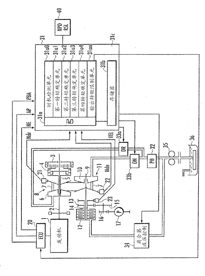
[0020] figure 1 It is a figure which shows the structure of the output torque control apparatus concerning embodiment of this invention. The present embodiment is an output torque control device for a vehicle having an engine (internal combustion engine) as a driving source, and a continuously variable transmission (CVT) is used as a transmission of the vehicle.

[0021] exist figure 1 Among them, the engine 1 of the vehicle is supported by an engine bracket, which is configured to absorb shocks with elastic bodies, and the drive shaft 2 that transmits the output from the engine 1 is connected to the input shaft 5 of the transmission via a forward / reverse switching mechanism 3 and a forward clutch 4 . link. The input shaft 5 is provided with a variable pulley (hereinafter referred to as “drive side pulley”) 8 capable of changing the V-groove width, that is, the winding diameter of the transmission belt 7 by means of the variable hydraulic cylinder 6 .

[0022] The drive bel...


PUM


Abstract

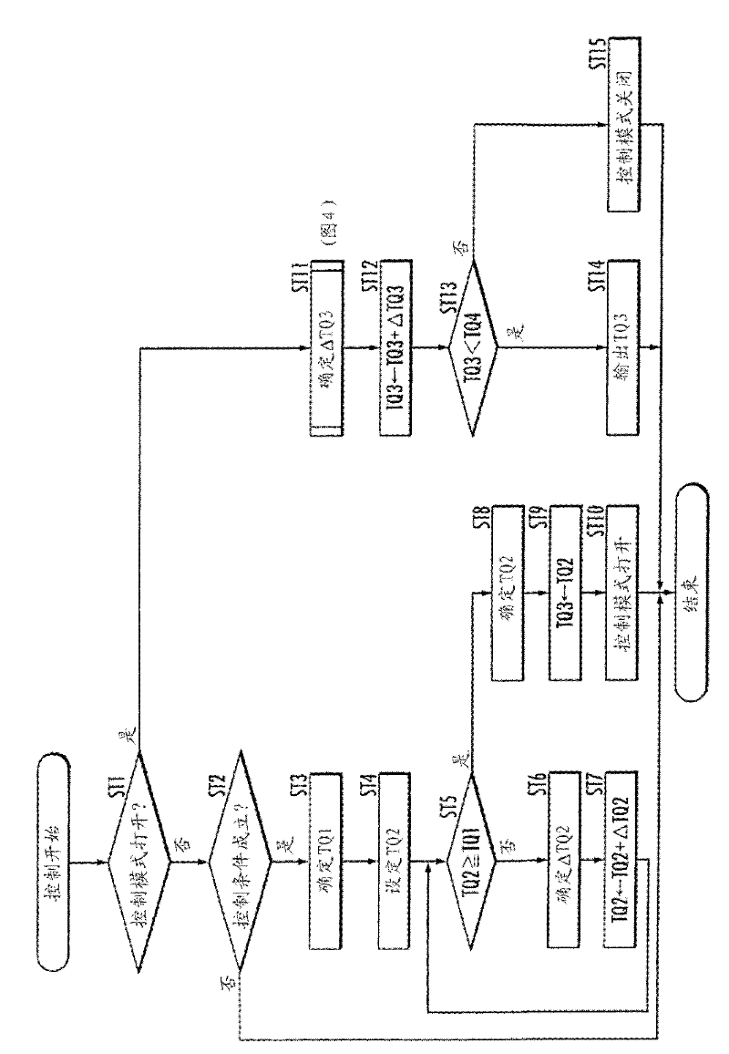
Output torque from a drive source is calculated as: a detection-timing torque which is determined when a value corresponding to the actuation of an accelerator pedal exceeds a predetermined value; a first torque which is determined on the basis of the vehicle speed and the transmission gear ratio; a second torque which is determined on the basis of the detection-timing torque and the first torque; a third torque which is determined on the basis of the control input of the accelerator pedal and the second torque; and a fourth torque which is determined on the basis of the control input of the accelerator pedal. The output torque is limited to the third torque only when the third torque is less than the fourth torque. The third torque is determined so that an increase in the third torque value is suppressed more when the detection-timing torque is larger than the first torque than when the detection-timing torque is not larger than the first torque.

Description

technical field [0001] The present invention relates to an output torque control device that controls the torque output from a drive source of the vehicle when the vehicle is started. Background technique [0002] Conventionally, as a control device that controls the output torque of a drive source when a vehicle starts, for example, a control device described in Patent Document 1 below has been proposed. According to this control device, the target output torque is set, and the output torque of the driving source is controlled so that the output torque approaches the target torque, so that when the vehicle is accelerated when the accelerator pedal is operated, it is possible to obtain smooth acceleration without affecting the acceleration response. [0003] Patent Document 1: Japanese Patent Laid-Open No. 2008-280926 [0004] However, when the actual output torque is controlled so that the actual output torque approaches the target torque, the control process becomes comp...

Claims


Application Information

Patent Timeline
Patent Type & Authority Applications(China)
IPC IPC(8): F02D45/00F02D29/00
CPCF02D2250/26F02D11/105B60W2520/10F02D2250/18B60W2540/10B60W2540/106B60W10/06F02D41/10B60W2710/105B60W2710/0666F02D29/02B60W10/107F02D2200/1002B60W30/188F02D41/0225B60W30/18027
Inventor 金泽智史藏田武嗣
Owner HONDA MOTOR CO LTD
Learn More