
Urea injection system by adopting gas pressure source

A urea injection system and gas pressure technology, which is applied to the electronic control, exhaust treatment, and exhaust devices of exhaust gas treatment devices, can solve the problem of high energy consumption of batteries, achieve optimal control, and improve measurement accuracy and stability. , the effect of eliminating adverse effects

Inactive Publication Date: 2011-11-16
中国第一汽车集团公司无锡油泵油嘴研究所
View PDF9 Cites 19 Cited by
  • Summary
  • Abstract
  • Description
  • Claims
  • Application Information

AI Technical Summary

Problems solved by technology

[0005] In order to solve the problem of high energy consumption of storage batteries in the prior art, the present invention provides a new SCR urea injection system using a gas pressure source

Method used


Image

  • Urea injection system by adopting gas pressure source
  • Urea injection system by adopting gas pressure source
  • Urea injection system by adopting gas pressure source

Examples


Embodiment Construction

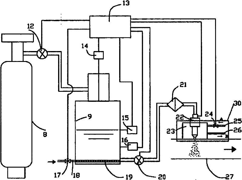
[0014] The invention is a urea injection system using a gas pressure source, wherein the gas pressure source can be a high-pressure gas storage bottle, or an air compressor and a gas storage tank. The first example is figure 1 shown. The high-pressure gas cylinder in this embodiment is a high-pressure nitrogen cylinder 8 with a working pressure of 35MPa. The second example is figure 2 shown. exist figure 2 Among them, a small air compressor is used to inflate the air storage tank 10 through the air charging valve 11 as a gas pressure source. The working pressure is 0.8MPa. The two embodiments have the same working principle except that the gas pressure source is different. The urea solution prepared according to the international standard ISO22241-1 is stored in the urea tank 9 . The urea tank 9 is a pressure vessel, which is pressurized by a gas pressure source, and the volume of the urea tank selected in this embodiment is 40L. Under the effect of pressure, the ure...


PUM


Abstract

The invention relates to a urea injection system by adopting a gas pressure source. The system is characterized by comprising a urea jar, a filter, a urea nozzle, a pressure sensor, a temperature sensor and an electric control unit, wherein the system comprises a gas pressure source and a pressure regulating stabilizer which are connected with the main pipeline of the system; the urea solution for injection is pressurized by utilizing the stable gas pressure; and an electric urea pump is not arranged in the system. The system provided by the invention has the advantages of simple structure, stable pressure and high injection metering accuracy.

Description

technical field [0001] The present invention relates to a urea injection system for post-treatment of diesel engine exhaust, which belongs to the exhaust gas purification system of internal combustion engines; more specifically, it relates to a urea solution that uses a gas pressure source to inject a urea solution to the exhaust system of a diesel engine to reduce the NOx of a diesel engine The exhausted SCR (Selective Catalyst Reduction) selective catalytic reduction system. Background technique [0002] In order to realize urea injection, the existing SCR urea injection system generally uses a DC electric pump to pressurize the urea solution. In automobiles and other vehicles and ships, the battery needs to supply power to the electric pump, which increases the power loss of the battery. Some existing technologies, such as the CN1965153A (WO2005 / 106220) patent of Bosch Corporation of Japan, also use electric heaters to heat the urea solution, which further increases the ...

Claims


Application Information

Patent Timeline
IPC IPC(8): F01N3/20F01N9/00B01D53/94
CPCY02T10/47Y02T10/24Y02T10/12Y02T10/40
Inventor 吴君华居钰生缪雪龙徐秀华朱明健孔亮王晓勇
Owner 中国第一汽车集团公司无锡油泵油嘴研究所
Learn More