


Quick Research
Generate reliable direction feasibility study reports for your R&D in just a few steps.

Technical Q&A
Discover and master advanced knowledge NOW. Basics, ideas, possibilities, all at once.

Find Solutions
As an expert in R&D theories, this can generate solutions to your technical problems instantly.

Evaluate Feasibility
Analyze your overall solution with one click, know your potential R&D risks in advance.

Monitor Landscape
Get weekly tech updates, stay abreast of the latest tech innovations and key insights.
Impulsive force generating set
A power generation device and impulse technology, applied in the field of power generation using impulse kinetic energy, can solve the problems of long time, impact on impulse, large displacement, etc.
- Summary
- Abstract
- Description
- Claims
- Application Information
AI Technical Summary
Problems solved by technology
Method used
Image

Examples
Embodiment 1
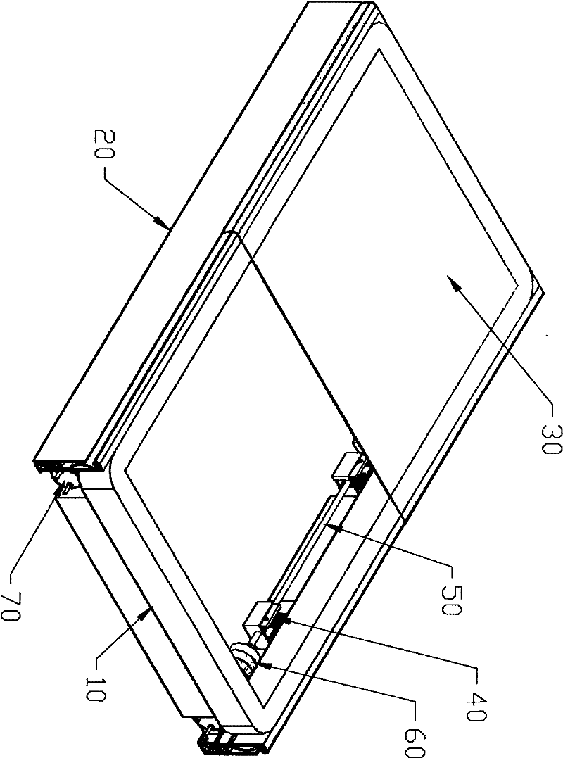
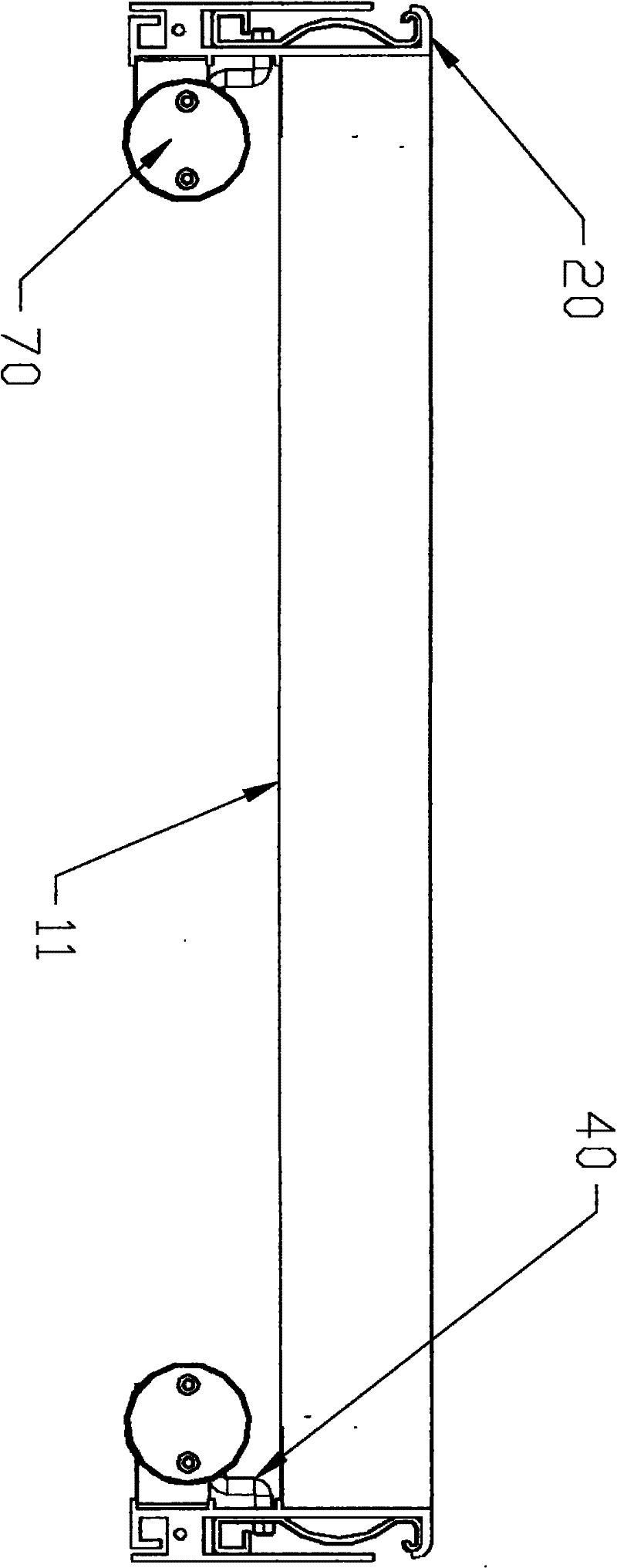
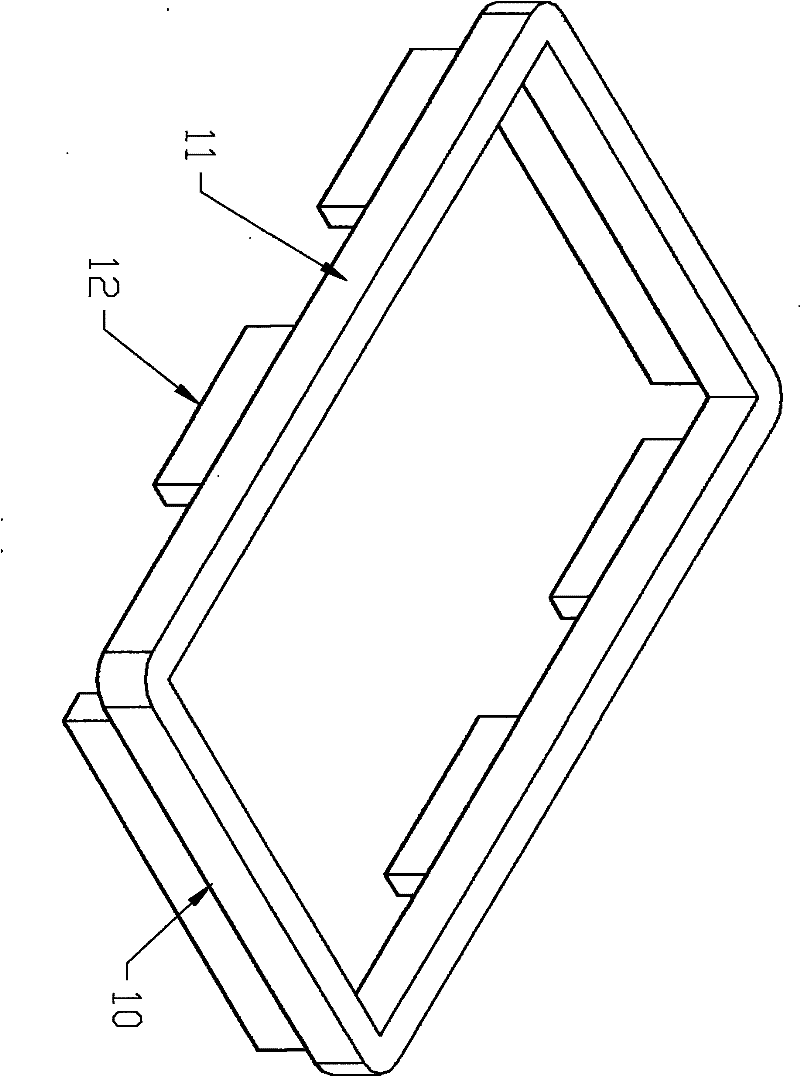
[0049] An impulsive power generating device, such as figure 1 As shown, it consists of a frame system 10, a material connection system 20, a material 30, a transmission system 40, a transmission rod 50, a planetary gear speed increaser 60 and a generator 70. figure 2 Shown are the connections of frame 11 , panel connection system 20 , drive system 40 and generator 70 . Wherein, the frame system 10 is as image 3 As shown, it is made up of a rectangular frame 11 and a frame foot 12. The rectangular frame 11 is bent into a rectangular frame by a rectangular steel pipe. The frame foot 12 is made of rectangular steel pipe or other materials. The rectangular frame 11 is connected with the frame foot 12 by screws.
[0050] The combination of the fabric connection system 20 and the fabric 30 is as follows: Figure 4 shown. The fabric connecting system 20 is composed of a base 21 , a rotating connecting elastic piece 22 , a cloth pressing profile 23 , a plug 24 and a connecting...
Embodiment 2
[0058] Figure 22 and 23 Shown is the second transmission system 80, made up of wire rope A, ratchet reel B, wire rope C, ratchet reel D, carriage 81, bracket 42 and "Z" shaped connecting rod 43. The connection of the wire rope A and the ratchet reel B is as follows: Figure 24 and 25 shown. The steel wire rope A is as Figure 26 As shown, there is a fixed head A1 formed by clamping the steel wire rope with an aluminum strip at each end, and the spiral groove B1 of the ratchet reel B is spiraled in the middle. Described ratchet reel B is as Figure 27 As shown, the outer ring has a spiral groove B1, and the inner ring has a through hole. The outer ring is slidingly connected to the inner ring. The steel wire rope A is spirally connected around the spiral groove B1 of the ratchet reel B in the middle. The structure, function and connection mode of the steel wire rope C and the ratchet reel D are the same as those of the steel wire rope A and the ratchet reel B. Describ...
PUM
 Abstract
Description
Claims
Application Information
 - R&D Engineer
- R&D Manager
- IP Professional
- Industry Leading Data Capabilities
- Powerful AI technology
- Patent DNA Extraction
Browse by: Latest US Patents, China's latest patents, Technical Efficacy Thesaurus, Application Domain, Technology Topic, Popular Technical Reports.
© 2024 PatSnap. All rights reserved.Legal|Privacy policy|Modern Slavery Act Transparency Statement|Sitemap|About US| Contact US: help@patsnap.com