Fitting member

A technology of parts and engaging parts, which is applied to vehicle parts, elastic suspensions, cantilevers mounted on pivots, etc., can solve the problems of dimensional tolerances, clutter, and the inability of the engaging surfaces to fit closely, and achieve a simple structure, Reliable and close contact effect

Inactive Publication Date: 2011-11-09
F TECH INC
View PDF4 Cites 10 Cited by
  • Summary
  • Abstract
  • Description
  • Claims
  • Application Information

AI Technical Summary

Problems solved by technology

[0008] However, according to the study of the present inventors, it is considered that in Patent Document 1 and Patent Document 2, the following structure is adopted: prepare a preliminary molded body in which protrusions and recesses are formed on a plate-shaped member in advance, and bend the preliminary molded body into a cylindrical shape. And the convex part and the concave part are fitted together, so the fitting itself is complicated, and, due to the dimensional tolerance existing in the convex part and the concave part, the engagement surface between the convex part and the concave part after fitting cannot be closely bonded, resulting in unnecessary gaps etc.
In particular, when the convex portion and the concave portion are formed into a tapered shape to form a dovetail joint type fitting, the fitting itself is difficult, and even if it is forcibly fitted by prying and tearing, the gap between the convex portion and the concave portion will be broken. There is also a strong tendency that the engaging surface of the
[0009] In addition, in Patent Document 2, in order to increase the joint strength of the joint portion having the convex portion and the concave portion, the joint portion is welded, but this welding itself is an additional operation, and when considering the subsequent bonding process and insertion process, It is also necessary to cut the welded portion smoothly, making it a more complicated structure

Method used


Image

  • Fitting member
  • Fitting member
  • Fitting member

Examples


no. 1 Embodiment approach

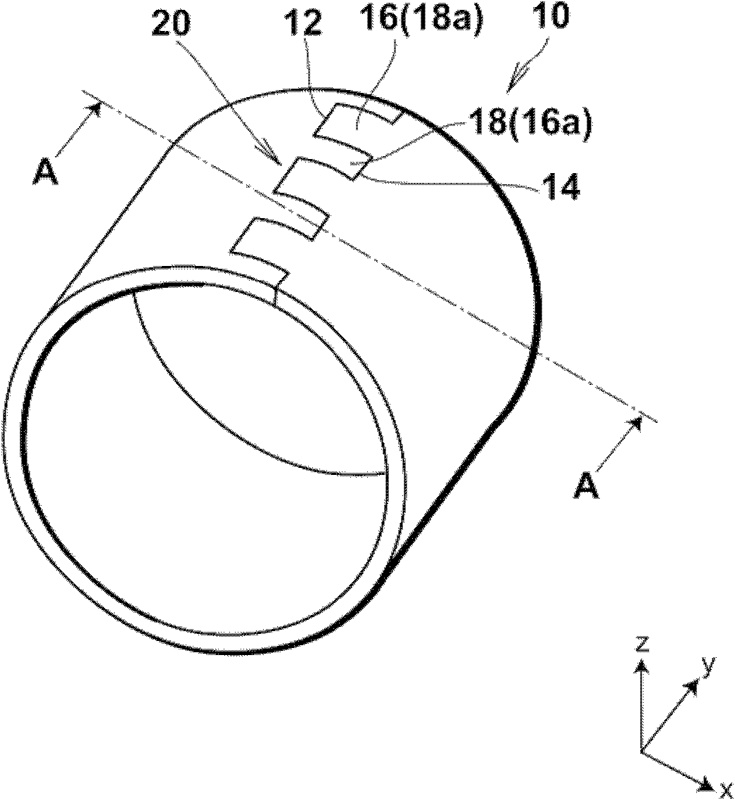
[0040] First, refer to figure 1 - Fig. 5 The collar of the first embodiment of the present invention will be described in detail.

[0041] figure 1 It is a perspective view of the collar of this embodiment.

[0042] Such as figure 1As shown, a cylindrical collar 10 made of metal such as iron or aluminum having a central axis in a direction parallel to the y-axis has one end 12 and the other end opposite to each other in the circumferential direction. 14. Here, when the collar 10 is a cylindrical member, it may have a square cylindrical shape other than a cylindrical one, and the cross-sectional shape cut in the x-z plane may be asymmetrical.

[0043] More specifically, one end portion 12 of the collar 10 has a plurality of protrusions 16 aligned in the axial direction, and recesses 16 a are formed correspondingly between the protrusions 16 . Here, when the protrusions 16 located at both ends in the axial direction have remaining portions adjacent to the outer side in the ...

no. 2 Embodiment approach

[0065] Next, refer to Figure 6 - Fig. 9 The collar of the second embodiment of the present invention will be described in detail.

[0066] Figure 6 It is a perspective view of the collar of this embodiment.

[0067]The main difference between the collar 100 of this embodiment and the first embodiment is that the structure of the fitting structure 120 is different, and the rest of the structure is the same. Therefore, in this embodiment, description will be made focusing on this difference, the same reference numerals will be attached to the same configuration, and the description will be simplified or omitted as appropriate.

[0068] Specifically, as Figure 6 As shown, the collar 100 has end portions opposite to each other in the circumferential direction, that is, one end portion 112 and the other end portion 114, and the one end portion 112 and the other end portion 114 are in contact with each other. 116. An engaging piece 118 made of metal such as iron or aluminum ...


PUM


Abstract

The invention provides a fitting member capable of ensuring strength in a necessary and sufficient manner with a simplified structure without using a welding process or the like. A fitting member (10, 100) is provided with a first end portion (12, 112), a second end portion (14, 114) facing to the first end portion, and a fitting structure (20, 120) having a first engagement portion (16, 16a, 118) and a second engagement portion (18, 18a, 116) to connect the first end portion and the second end portion with each other by fitting the first engagement portion and the second engagement portion with each other. The fitting structure is defined by making the first engagement portion and the second engagement portion engaged with each other, while making the second engagement portion formed by punching a preform body of the fitting member through the first engagement portion.

Description

technical field [0001] The present invention relates to a fitting member, and particularly relates to a fitting member usable as a strength member of vehicles such as automobiles. Background technique [0002] In recent years, anti-vibration parts such as various brackets and bushings have been used in chassis parts of vehicles such as automobiles. However, the anti-vibration parts are made of rubber, and generally adopt a structure in which the rubber part is bonded to a metal part. A cylindrical collar, or it is inserted into a collar provided on a strength member such as a beam or an arm. [0003] The collar needs to maintain high adhesiveness in the anti-vibration member and mountability to the strength member, but since it is a strength member, it is also required to maintain high strength of the collar itself. [0004] Under such circumstances, Patent Document 1 proposes a bush-type anti-vibration rubber in which a convex portion 5 and a concave portion 6 are formed a...

Claims


Application Information

Patent Timeline
Patent Type & Authority Applications(China)
IPC IPC(8): B60G11/12B60G7/00F16C13/00
CPCF16F1/3842
Inventor 长堀胜美伊豆透
Owner F TECH INC
Why Eureka
Try Eureka