
Pipe fitting expanding device

A technology of equipment and pipe fittings, which is applied in the field of pipe fittings flaring equipment, can solve the problems of unsightly finished products, high cost, and low efficiency of thermal flaring processing, etc.

Inactive Publication Date: 2011-10-26
SHANGHAI CHANGYUAN ELECTRONICS MATERIAL +1
View PDF9 Cites 4 Cited by
  • Summary
  • Abstract
  • Description
  • Claims
  • Application Information

AI Technical Summary

Problems solved by technology

[0006] The purpose of the present invention is to provide a pipe fitting flaring equipment to solve the existing technical problems of thermal flaring processing such as low efficiency, high cost, and unsightly finished products.

Method used


Image

  • Pipe fitting expanding device
  • Pipe fitting expanding device
  • Pipe fitting expanding device

Examples


Embodiment Construction

[0016] In order to make the above-mentioned features and advantages of the present invention more comprehensible, exemplary embodiments are given below together with accompanying drawings and described in detail as follows.

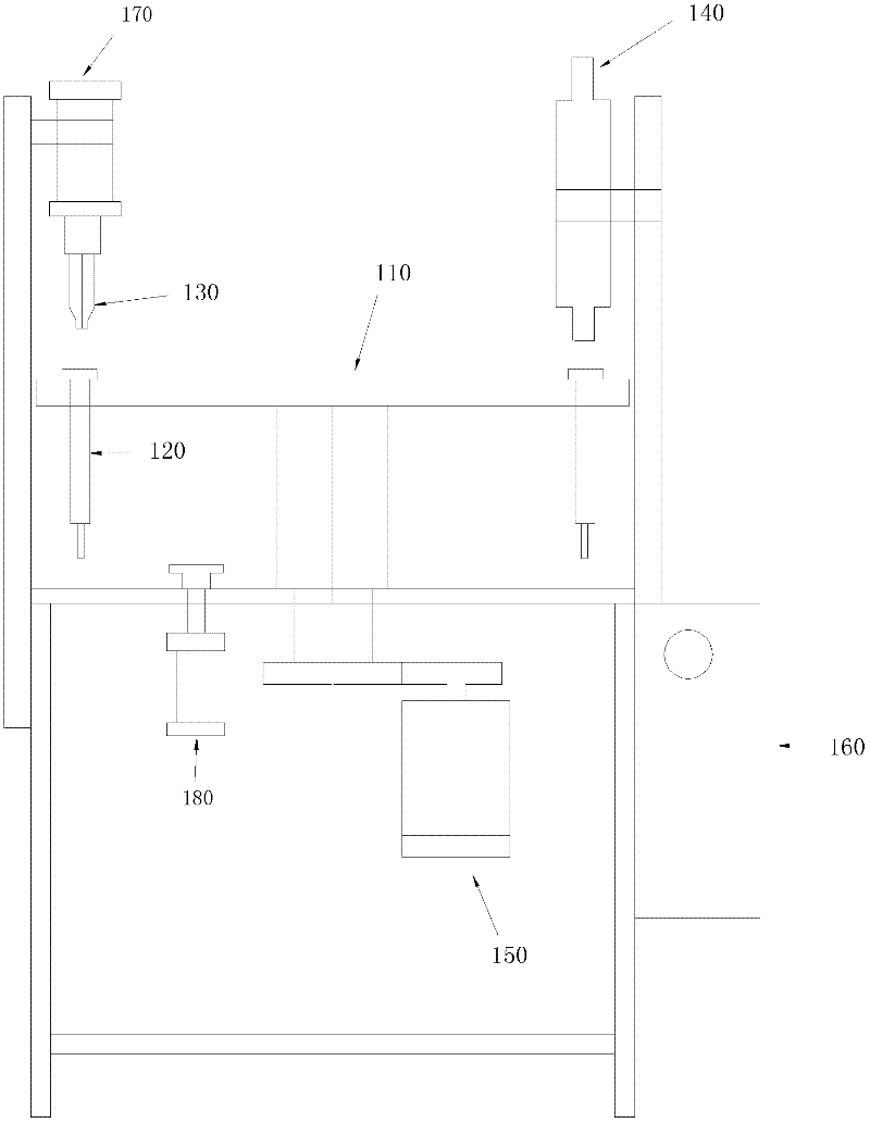
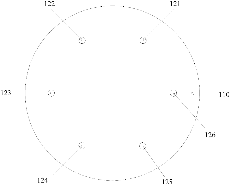
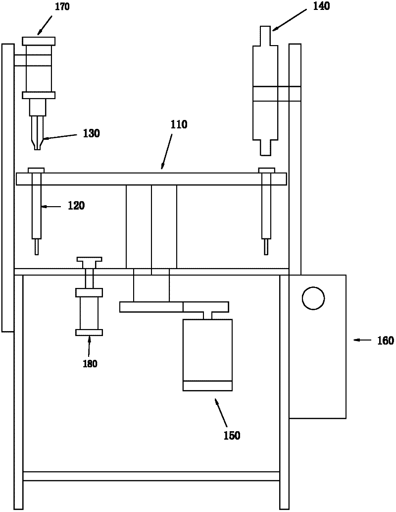
[0017] Please refer to figure 1 , which is a structural schematic diagram of a pipe flaring device provided by an embodiment of the present invention. As shown in the figure, the apparatus includes a table 110 , a lower mold 120 , an upper mold 130 , a heater 140 , a rotating motor 150 and a controller 160 . The lower mold 120 is arranged on the workbench 110 for storing pipes to be flared; the upper mold 130 and the heater 140 are arranged above the workbench; the rotating motor 150 is connected with the workbench 110 to drive the workbench to rotate. The controller 160, as the core of the flaring equipment, is used to coordinate the orderly work among various components and realize flaring automation. Specifically, the controller 160 controls the rota...


PUM


Abstract

The invention discloses a pipe fitting expanding device, which comprises: a work bench; a bottom mold which is disposed on the work bench and is used to store a pipe fitting to be expanded; an upper mold which is disposed above the work bench; a heater which is disposed above the work bench; a rotary motor which is connected to the work bench; a controller which controls the rotary motor to drive the work bench to rotate so as to move the bottom mold to a position below the upper mold or the heater, controls the heating temperature and time of the heater, and controls both the upper mold and the bottom mold to extrude the orifice of the pipe fitting to be expanded. The device realizes an automatic expanding process of pipe fittings, and can reduce labor cost and increase production efficiency, and products processed by the device has uniform and beautiful appearances.

Description

technical field [0001] The invention relates to the technical field of pipe fitting processing and manufacturing, in particular to a pipe fitting flaring device. Background technique [0002] In the processing and manufacturing process of pipe fittings, it is often necessary to expand the pipe fittings. The existing flaring processing methods include cold expanding technology and hot expanding technology. [0003] Cold flaring technology is to use external force to force the nozzle to deform at room temperature, such as forming a trumpet-shaped nozzle. However, during the cold flaring process, the stress is concentrated, and the material is easy to decompose and crack. Thermal flaring technology takes into account that thermoplastic materials such as polypropylene (PP), polyethylene (PE), and polyvinyl chloride (PVC) will undergo viscous flow at their melting temperature, and use this principle to expand thermoplastic pipe fittings or The device is heated to near the melti...

Claims


Application Information

Patent Timeline
Patent Type & Authority Applications(China)
IPC IPC(8): B29C57/02
Inventor 翁妙峰
Owner SHANGHAI CHANGYUAN ELECTRONICS MATERIAL
Learn More