
Self-adaptive wireless charging system

A wireless charging and self-adaptive technology, applied in electromagnetic wave systems, current collectors, electric vehicles, etc., can solve the problems of environmental temperature and air humidity, easy to generate sparks, short transmission distance, etc., to improve stability and operation efficiency , the effect of reducing energy loss and reducing additional loss

Active Publication Date: 2011-10-19
WUHAN ZHONGYUAN ELECTRONICS GRP
View PDF2 Cites 45 Cited by
  • Summary
  • Abstract
  • Description
  • Claims
  • Application Information

AI Technical Summary

Problems solved by technology

[0002] With the vigorous development of high-tech industries such as electric vehicles, high-speed rail, and wireless sensor networks, and the application of electronic equipment in more and more occasions, the traditional wired power supply method has exposed many limitations, and the battery power supply has caused a lot of problems. Waste of resources and environmental pollution, high current contact power supply itself has serious line loss and repeated plugging and unplugging line loss, which is obviously affected by ambient temperature and air humidity, and sparks are easy to generate, so the reform of power supply mode is imperative
However, the traditional wireless power supply method has strong radiation, low transmission efficiency, and short transmission distance, which limits the promotion of related applications. At the same time, the transmission power of wireless power supply cannot be controlled in the existing technology, and the work efficiency is low.

Method used


Image

  • Self-adaptive wireless charging system
  • Self-adaptive wireless charging system
  • Self-adaptive wireless charging system

Examples


Embodiment

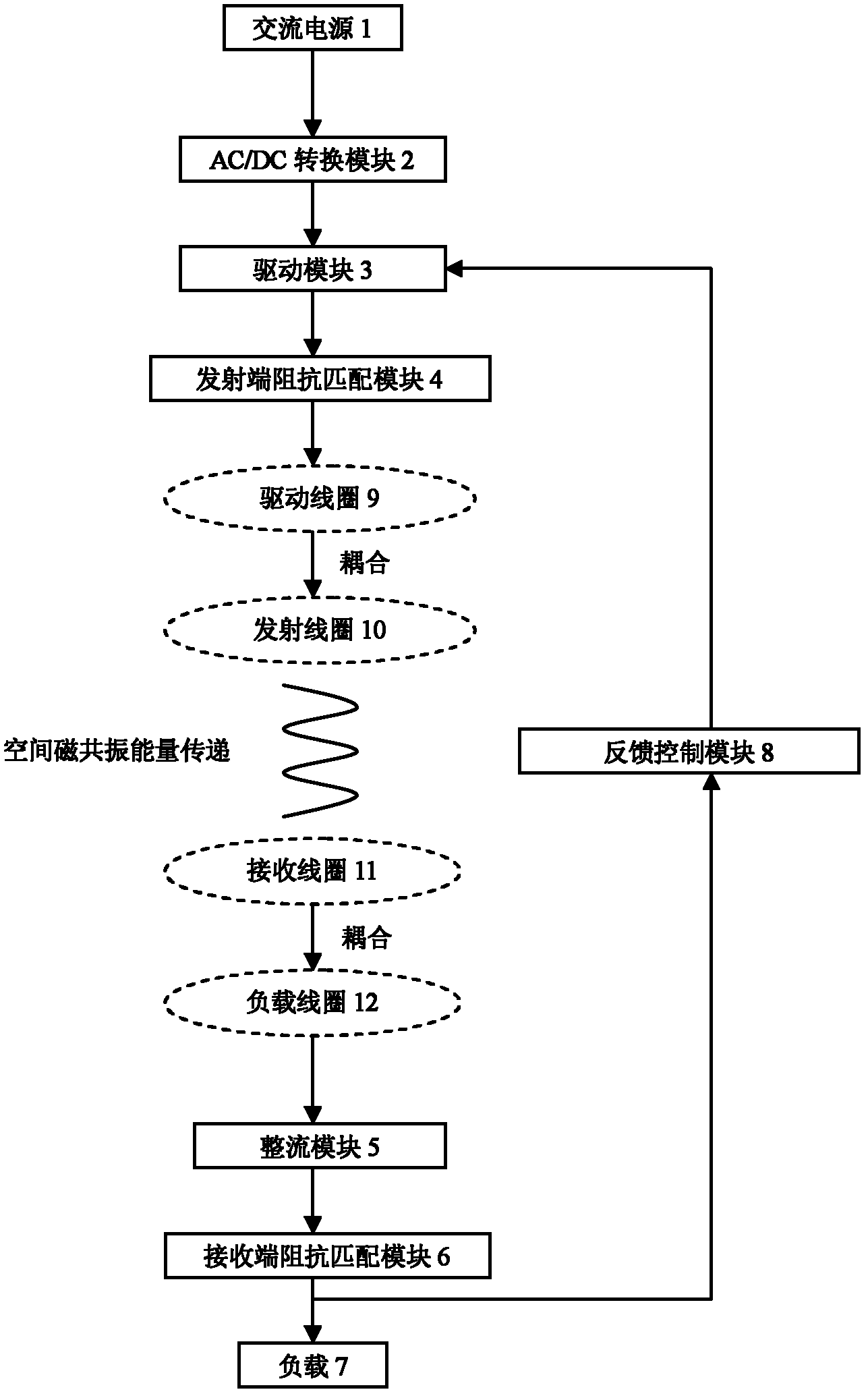
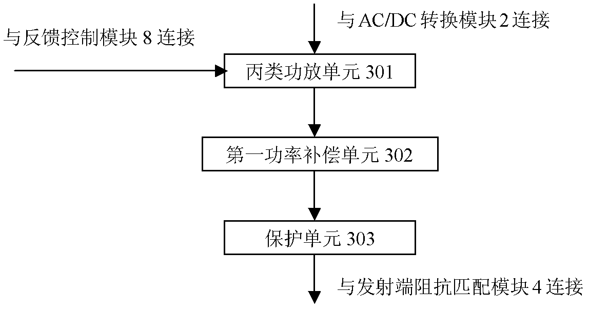
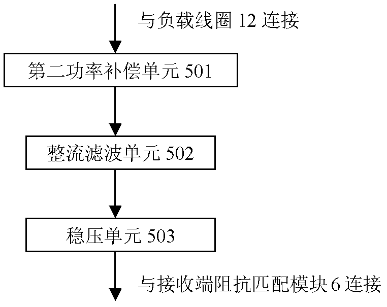
[0020] Such as figure 1 As shown, an adaptive wireless charging system includes an AC power source 1, a load 7, an AC / DC conversion module 2, a drive module 3, a transmitter impedance matching module 4, a drive coil 9, a transmitter coil 10, a receiver coil 11, a load Coil 12 , rectification module 5 , receiving end impedance matching module 6 and feedback control module 8 . The AC power supply 1 is connected to the driving coil 9 through the sequentially connected AC / DC conversion module 2, the driving module 3 and the transmitting end impedance matching module 4, and the driving coil 9 is coupled to the transmitting coil 10, and the transmitting coil 10 transmits information to the The receiving coil 11, the receiving coil 11 is coupled and connected with the load coil 12, the load coil 12 is connected with the receiving end impedance matching module 6 through the rectification module 5, the output of the receiving end impedance matching module 6 is connected with the load 7...


PUM


Abstract

The invention discloses a self-adaptive wireless charging system, comprising an alternating-current power supply, a load, an AC (alternating current) / DC (direct current) conversion module, a driving module, a driving coil, an emitting coil, a receiving coil, a load coil, a rectifying module, a receiving end impedance matching module and a feedback control module, wherein the alternating-current power supply is connected with the driving coil by the AC / DC conversion module, the driving module, the emitting end impedance matching module and the driving coil that are sequentially connected with one another; the driving coil is coupled with the emitting coil; the emitting coil can transfer energy to the receiving coil by magnetic resonance coupling; the receiving coil is coupled with the loadcoil; the load coil is connected with the load by the rectifier module and the receiving end impedance matching module that are connected with each other sequentially; and the receiving end impedancematching module is connected with the driving module by the feedback control module. The self-adaptive wireless charging system can control the transmitting power of the wireless power supply, can improve the stability and running efficiency of the system, can improve the power factor of the system by a power compensation unit, and can reduce energy loss.

Description

technical field [0001] The invention belongs to the technical field of wireless charging, and more specifically relates to an adaptive magnetic resonance wireless charging system, which is suitable for power supply needs in special occasions such as household appliances, handheld mobile devices, electric vehicles, wireless sensor networks, and medicine. Background technique [0002] With the vigorous development of high-tech industries such as electric vehicles, high-speed rail, and wireless sensor networks, and the application of electronic equipment in more and more occasions, the traditional wired power supply method has exposed many limitations, and the battery power supply has caused a lot of problems. The waste of resources and environmental pollution, high-current contact power supply itself has serious line loss and repeated plugging and unplugging line loss, which is significantly affected by ambient temperature and air humidity, and sparks are prone to occur. The re...

Claims


Application Information

Patent Timeline
IPC IPC(8): H02J7/02H02J17/00H02J50/12
Inventor 张东华贺智轶梁金峰梁曦黄秋元
Owner WUHAN ZHONGYUAN ELECTRONICS GRP
Learn More