
Passive optical splitter and passive optical network system

A technology of splitter and passive light, which is applied in the field of optical communication, can solve problems such as light leakage and loss, achieve the effect of reducing leakage loss and improving uplink transmission efficiency

Active Publication Date: 2011-10-12
HUAWEI TECH CO LTD
View PDF5 Cites 10 Cited by
  • Summary
  • Abstract
  • Description
  • Claims
  • Application Information

AI Technical Summary

Problems solved by technology

[0005] The embodiment of the present invention provides a POS and a PON, which are used to solve the problem of light leakage in the upstream direction of the passive optical splitter in the prior art and cause light loss, so as to reduce the light loss of the upstream transmission, thereby Improve uplink transmission efficiency

Method used


Image

  • Passive optical splitter and passive optical network system
  • Passive optical splitter and passive optical network system
  • Passive optical splitter and passive optical network system

Examples


Embodiment Construction

[0021] The following will clearly and completely describe the technical solutions in the embodiments of the present invention with reference to the accompanying drawings in the embodiments of the present invention. Obviously, the described embodiments are only some, not all, embodiments of the present invention. Based on the embodiments of the present invention, all other embodiments obtained by persons of ordinary skill in the art without making creative efforts belong to the protection scope of the present invention.

[0022] Figure 2A It is a top view of the structural schematic diagram of the POS according to Embodiment 1 of the present invention. Figure 2B It is the left view of the schematic structural diagram of the POS in Embodiment 1 of the present invention. by Figure 2A For example, Figure 2A As shown, the POS can be a low-loss passive optical splitter (Loss-low Passive Optical Splitter, LPOS for short), and the structure of the POS includes: at least two spl...


PUM


Abstract

The invention provides a passive optical splitter and a passive optical network system. The passive optical splitter comprises at least two branching monomode waveguides, at least a united monomode waveguide, and at least a tapered waveguide, wherein one end of the tapered waveguide is at least coupled respectively to two branching monomode waveguides, with the other end of the tapered waveguide coupled to at least one united monomode waveguide; and the core layer of the tapered waveguide is made of optical induced refractive index changing materials. By adopting the passive optical splitter and the passive optical network system, with the core layer of the tapered waveguide of the passive optical splitter adopting optical induced refractive index changing materials, the leakage wastage of the optical signals can be reduced and the efficiency of the uplink transmission can be improved by limiting optical transmission via enhancing refringence of positions having optical fields of different intensity in core layer when optical signals are transmitted.

Description

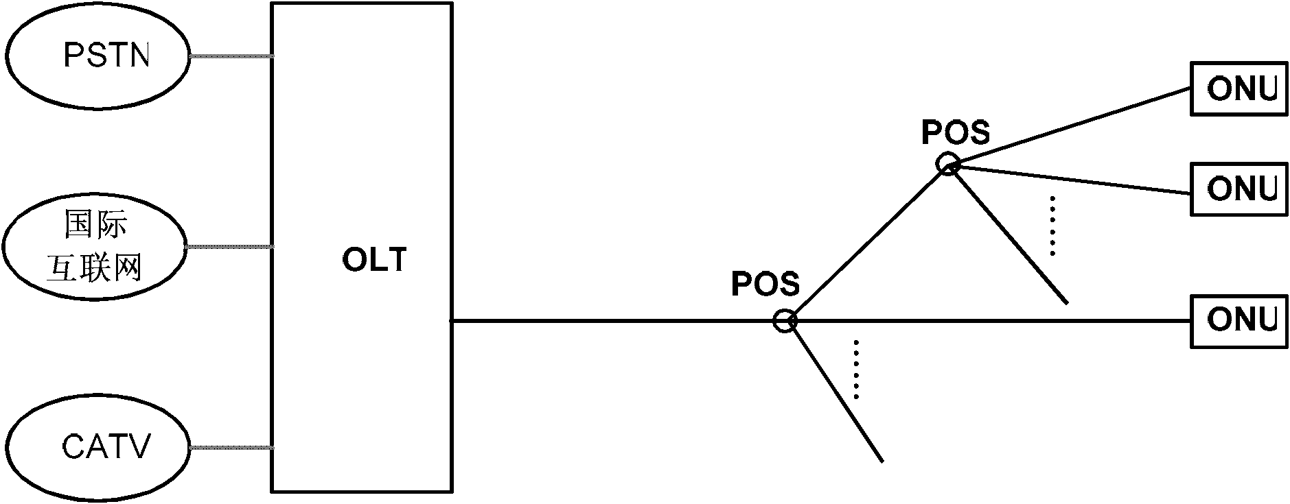
technical field [0001] Embodiments of the present invention relate to optical communication technologies, and in particular to a passive optical splitter (Passive Optical Splitter, POS for short) and a passive optical network system (Passive Optical Network, PON for short). Background technique [0002] With the increase of users' demand for network bandwidth, the traditional copper broadband access network is facing a bandwidth bottleneck, and the optical fiber access network has become a strong competitor for the next-generation broadband access network. Among various optical fiber access networks, the passive optical network (Passive Optical Network, PON for short) system is the most competitive. [0003] figure 1 It is a schematic structural diagram of an existing PON system. Such as figure 1 As shown, the existing PON system includes: an optical line terminal (Optical Line Terminal, referred to as OLT) located at the central office, at least one passive optical split...

Claims


Application Information

Patent Timeline
Patent Type & Authority Applications(China)
IPC IPC(8): G02B6/125H04Q11/00H04B10/272
CPCG02B6/125G02B2006/1215G02B2006/12195H04B10/272G02F2202/13
Inventor 陈聪周小平赵峻王卫阳
Owner HUAWEI TECH CO LTD
Learn More