
Ingot mould used for casting iron alloy and casting method thereof

A cast iron alloy and ferroalloy technology, which is applied in the field of ferroalloy casting ingot mold, cast iron alloy ingot mold and casting field, can solve the problems of low economic benefit, high energy consumption, burning loss of ore raw material resources, etc., and achieve significant economic benefits, The effect of reducing labor intensity and improving production environment

Active Publication Date: 2011-10-12
四川川投峨眉铁合金(集团)有限责任公司
View PDF5 Cites 7 Cited by
  • Summary
  • Abstract
  • Description
  • Claims
  • Application Information

AI Technical Summary

Problems solved by technology

The poured ferroalloy block will produce a large amount of alloy fine powder surface slag during the mechanical coarse crushing process, hammering and mechanical secondary crushing process. According to actual production statistics: the alloy surface ratio is about 15% to 25%, that is, That is to say, the qualified product rate currently produced is generally only about 80%, and 15%~25% of the alloy fine powder surface slag cannot be used as steelmaking raw materials, and can only be re-melted or blended into ore raw materials to return to the furnace. Recycle smelting, which will lead to the loss of a large amount of valuable ore raw material resources, which is the main reason why the current ferroalloy products have high energy consumption and low economic benefits

Method used


Image

  • Ingot mould used for casting iron alloy and casting method thereof
  • Ingot mould used for casting iron alloy and casting method thereof
  • Ingot mould used for casting iron alloy and casting method thereof

Examples


Embodiment Construction

[0039] A kind of ingot mold that the present invention proposes is used for cast iron alloy, and it is made of mold body 1 and configuration

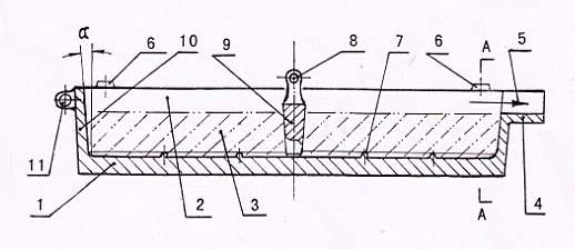
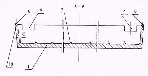
[0040] The demoulding iron 9 in the casting cavity 2 of the mold body 1 is formed, and the mold wall 10 around the mold body 1 is made into an outwardly inclined demoulding structure, for example: the length of the casting cavity 2 is 1800mm, the width is 1000mm, and the depth For an ingot mold with a rectangular structure of 180mm, the camber angle α of the mold wall 10 is set to 30o. This cambered demoulding structure design is particularly beneficial to the operation of removing iron from the mold; another example: the length of the casting cavity 2 is 3500mm For an ingot mold with a rectangular structure with a width of 2500 mm and a depth of 120 mm, the camber angle α of the mold wall 10 is set to 60o for a cambered demoulding structure, which is also conducive to the operation of removing iron from the mold. According to the speci...


PUM


Abstract

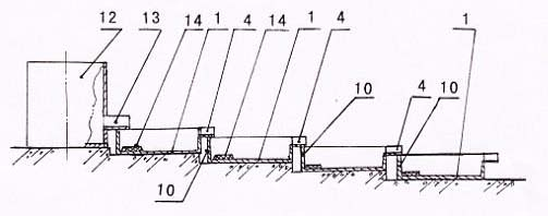
The invention provides an ingot mould used for casting an iron alloy and a casting method thereof. The casting method comprises the following steps of: mounting an ingot mould set provided with an iron runner into a stepped sequentially-cast arrangement structure in stepped fall positions, arranging the ingot moulds, assembling, demoulding and lifting iron, pouring molten iron, fetching the iron and demoulding, quenching with water and finishing to cast the iron alloy; when the temperature of an iron block is reduced to 700-1000 DEG C, fetching the iron, and quenching an alloy iron block at high temperature with water, thus internal metallographic structure is converted into crisp thick longitudinal columnar crystal and massive micro cracks are produced on the surface, and the crushing difficulty is greatly reduced. By adopting the ingot mould and the casting method provided by the invention, the production conditions can be obviously improved, the labour intensity is alleviated, the crushing processing efficiency and product particle size percent of pass are improved, the energy consumption is reduced, and the economic benefit is increased, and the ingot mould and the manufacturing method thereof have the advantages of simple structure, flexible mounting, convenience in casting operation and convenience in quenching of molten iron block at temperature with water, thus the ingot mould and the manufacturing method thereof have an excellent popularization and application prospect.

Description

Technical field: [0001] The invention relates to an ingot mold for casting ferroalloy, and also relates to a casting method and a water quenching method for a red-hot ferroalloy block, belonging to the technical field of ferroalloy production, in particular to an ingot mold for casting ferroalloy and its casting method. Background technique: [0002] At present, ferroalloy production usually adopts the following four casting methods: 1. Pit casting: clean the slag on the upper layer of molten iron in the ladle and then pour it into the pit. After the alloy is cooled, use a forklift to shovel it into the warehouse, and then process it to a qualified particle size. After sales; 2. Ingot mold casting: use cast iron ingot molds with a bottom thickness of more than 150mm and no molten iron overflow outlet to place independently, and move the ingot molds one by one with the ladle hanging on the crane, usually casting into a thickness of more than 200mm The product blocks are taken...

Claims


Application Information

Patent Timeline
IPC IPC(8): B22D7/06B22D7/12C21D1/18
CPCY02P10/20
Inventor 唐华应穆婷云郑再春吴孝杨君臣
Owner 四川川投峨眉铁合金(集团)有限责任公司
Learn More