Spiral spring

A coil spring, reed technology, applied in the direction of coil springs, springs/shock absorbers, chairs, etc., can solve the problems that do not involve spring and/or reclining adjustment mechanism, do not fully explain the pitch coil structure, etc.

Active Publication Date: 2011-09-28
日本泰克尼卡株式会社
View PDF8 Cites 2 Cited by
  • Summary
  • Abstract
  • Description
  • Claims
  • Application Information

AI Technical Summary

Problems solved by technology

[0011] In the schemes and inventions of the above-mentioned documents 1) to 6), there is no sufficient description of the pitch roll structure that is most suitable for the reclining adjustment mechanism, and there is an urgent need for room for improvement and further work.
In particular, in the solutions and inventions of these documents 1) to 6), there is no solution related to the spring and / or the return speed of the reclining adjustment mechanism, so it is not suitable for this reclining adjustment mechanism

Method used


Image

  • Spiral spring
  • Spiral spring
  • Spiral spring

Examples


Embodiment Construction

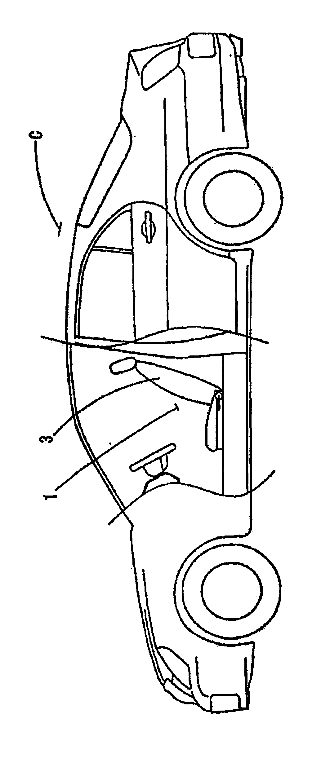
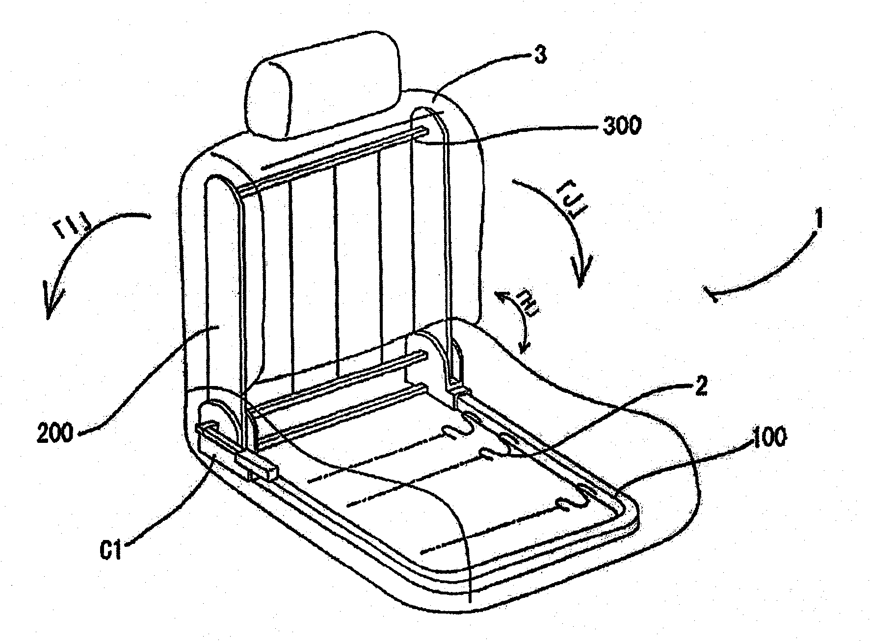
[0048] When describing the first embodiment, 1 in the figure is the first seat of the vehicle C, and the first seat 1 is mainly composed of a bottom frame 100 mounted on the floor and a pair of upper arms 200 mounted on the rear end side of the bottom frame 100. . Also, the bottom frame 100 is configured in the form of a rectangular frame in which a spring-like cushion frame 2 is installed. There is also a structure covered with polyurethane pads (not shown) and wool thick woolen seat pads (not shown) above the cushion frame 2 . The lower ends of the upper arms 200 , 200 (referred to as 200 ) are respectively attached to the left and right rear ends (in the forward direction) of the bottom frame 100 so as to be movable in the front-rear direction (arrow H). In addition, upper ends of the respective upper arms 200 are coupled to each other by a link 300 having a length approximately equal to the left and right width of the bottom frame 100 , whereby the left and right upper ar...


PUM


Abstract

A spiral (coiled) spring used for a vehicle and more particularly for a reclining adjusting mechanism for a vehicle seat. The spiral spring which is a spring plate member constructed from a band-like steel plate having high hardness has ridges formed on opposite ends in the coiling direction of the spring plate member so that the ridges project from the surfaces of the spring plate member and that the surfaces of the projected ridges are curved. The spring plate member has an outer end section, an intermediate section extending from the outer end section, and an inner end section extending from the intermediate section, and the spring plate member has a pitch coiled structure. In the pitch coiled structure, an engagement section bent in the radial direction is formed at the end of the outer end section, an engagement coiled core section is formed on the inner end section, and a gap between the intermediate section and the inner end section is set smaller than a gap between the outer end section and the intermediate section. The spiral spring reliably achieves both winding of the spiral spring (backrest is smoothly tilted to a rear position) and restoration of the spring to the original state (the backrest is smoothly returned to a forward position), which are characteristics of spiral springs. Also, abrasion, catching, and frictional noise at the time of contact can be avoided. Further, metal fatigue of the spiral spring can be reduced.

Description

technical field [0001] The invention relates to a coil spring used in a reclining adjustment mechanism arranged in a vehicle seat frame, and relates to a scroll spring formed by making a high-hardness steel strip (reed) into a scroll. Background technique [0002] In the past, this (reclining mechanism) coil spring was constructed so that it was coiled up (tensioned) when the seat back was reclined, uncoiled (relaxed) and returned to its original position when the seat back was raised forward shape. [0003] However, in conventional coil springs, the opposing reed inner and outer surfaces (reed surfaces) contact each other and / or rub against each other during the winding process, and the winding of the inner and outer surfaces at the rubbed place is restricted and stopped, or Continue crimping at an angle. In such a state, the performance of the spring cannot be fully exerted, such as correct winding or unwinding, and there is discomfort that the seat back cannot be reclin...

Claims


Application Information

Patent Timeline
Patent Type & Authority Applications(China)
IPC IPC(8): F16F1/10A47C1/024B21D53/00
CPCB60N2/2356F16F1/10B60N2/236
Inventor 山田伸雄
Owner 日本泰克尼卡株式会社
Why Eureka
Try Eureka