
Superhigh-efficiency brazed motor rotor

An electric motor, ultra-efficient technology, applied in the direction of magnetic circuit rotating parts, magnetic circuit shape/style/structure, etc., can solve the problems of difficulty in die-casting process, increase of stray loss of transverse harmonic current, increase of motor cost, etc., to achieve The effect of simple equipment tooling, reducing stray loss, and reducing temperature rise

Inactive Publication Date: 2011-09-28
福建惠丰电机有限公司
View PDF6 Cites 7 Cited by
  • Summary
  • Abstract
  • Description
  • Claims
  • Application Information

AI Technical Summary

Problems solved by technology

[0003]1. The melting point of cast copper is about 1100°C, which is about 400°C higher than that of cast aluminum, so it brings great difficulty to the die-casting process and the pass rate is low
[0004]2. Die-casting molds must be resistant to high temperatures and must be manufactured with special materials and special processes
In fact, the current mold life is not long enough, and the cost is also high
About 4,000 die-casting copper rotor molds are about to be scrapped, which is one of the reasons for the increase in the cost of the motor
[0005] 3. The cast copper rotor adopts the die-casting process. Because the copper guide bar is closely attached to the groove wall under high temperature and high pressure strength, the contact resistance becomes small, and the stray loss caused by the transverse harmonic current increases, which affects the increase in motor efficiency.
[0006]4. Casting copper rotors is not only technically difficult, but also requires imported high-precision and advanced die-casting equipment
Due to the large investment, it is difficult for ordinary enterprises to bear

Method used

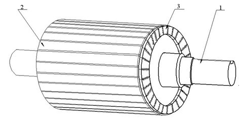
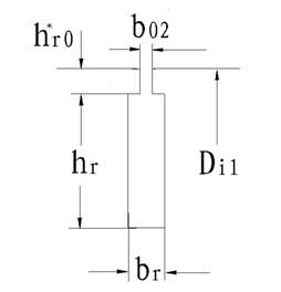
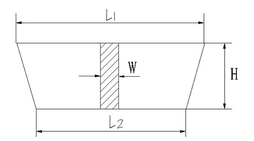

Image

  • Superhigh-efficiency brazed motor rotor
  • Superhigh-efficiency brazed motor rotor
  • Superhigh-efficiency brazed motor rotor

Examples


Embodiment

[0045] This embodiment design rated voltage 380V, rated frequency 50Hz, Wiring, sealed self-fan cooling, protection class IP55, insulation class F, N design for general use. According to the national standard GB18613-2006 "small and medium-sized three-phase asynchronous motor energy efficiency limit value and energy efficiency level" the highest level and related standards assessment. The motor efficiency is determined according to the loss analysis method B in GB / T1032-2005 "Test methods for three-phase asynchronous motors".

[0046] See Table 1 and Table 2 for motor structural parameters and performance target targets (including energy efficiency limit values ​​including rated output power and 75% rated output power efficiency). The model, rated power and number of poles of the embodiment are as follows:

example 1

[0047] Example 1: CGX132S1-2, 5.5kW, 2 poles;

example 2

[0048] Example 2: CGX132S-4, 5.5kW, 4 poles;


PUM


Abstract

The invention relates to a manufacturing process for a superhigh-efficiency brazed motor rotor, which belongs to the technical field of motor manufacturing and is applied to standard cage three-phase and single-phase asynchronous motors. The efficiency of the motor is improved, energy is saved and the efficiency is improved. The rotor of the embodiment of the invention adopts a core with parallelgrooves, and adopts rectangular copper bars. One end of each conducting bar is L-shaped, the conducting bar forms a Z shape after being inserted into the grooves, and the two ends of the conducting bar are welded to form end rings, thereby forming the whole high-efficiency brazed motor rotor. In the manufacturing process, equipment and tools are simple, and the rotor can be produced only by ordinary enterprise equipment without expensive die casting machines, die casting moulds and high-temperature copper melting electric furnaces. The manufacturing process is simple and convenient, and a barinsertion process and argon tungsten-arc welding are adopted. Insulating layers are arranged between the conducting bars in the grooves and groove walls so as to reduce stray loss produced by the medium and high frequency lateral current of the rotor and achieve favorability for reducing temperature and improving the efficiency. The efficiency of the motor can reach superhigh efficiency which is the highest of international GB18613-2006 'minimum allowable values of energy efficiency and the energy efficiency grades for mall and medium three-phase asynchronous motors'.

Description

technical field [0001] The invention relates to a copper-welded rotor of an ultra-high-efficiency motor, which is suitable for standard series squirrel-cage three-phase and single-phase asynchronous motors. Background technique [0002] At present, the development and application of high-efficiency motors is an international development trend, and all countries in the world attach great importance to the energy-saving work of motors. my country is no exception. The energy efficiency standard "Limitable Values ​​of Energy Efficiency and Energy Efficiency Grades of Small and Medium-sized Three-phase Asynchronous Motors" (GB18613-2006) has been implemented on July 1, 2007. This standard is nationally mandatory. The average efficiency index of three-phase asynchronous motors in my country is about 3 to 5 percentage points lower than that of the international ones, especially for single-phase motors, which must catch up with the advanced level within a few years. For this reaso...

Claims


Application Information

Patent Timeline
IPC IPC(8): H02K1/26
Inventor 孙学政杨良弟
Owner 福建惠丰电机有限公司
Learn More