
Antenna device and radio communication device

An antenna device and antenna part technology, applied in the field of antenna devices and wireless communication devices, can solve the problems of large antenna device size, unusability, and inability to achieve high isolation, and achieve the effects of miniaturization, improved isolation, and high efficiency

Active Publication Date: 2011-09-14
PANASONIC INTELLECTUAL PROPERTY CORP OF AMERICA
View PDF5 Cites 11 Cited by
  • Summary
  • Abstract
  • Description
  • Claims
  • Application Information

AI Technical Summary

Problems solved by technology

[0013] In the configurations of Patent Documents 1 and 2, although the resonance frequency can be changed, there is only one power supply unit, so there is a problem that it cannot be used in MIMO communication, communication using a diversity method, or an adaptive array (adaptive array).
[0014] In addition, in the structure of Patent Document 3, since there are a plurality of feeding parts, it can be used in MIMO communication, communication using a diversity method, or an adaptive array, but high isolation cannot be achieved in a plurality of frequencies, and the antenna element The spacing needs to be λ / 2, and there is a problem that the size of the antenna device becomes larger

Method used


Image

  • Antenna device and radio communication device
  • Antenna device and radio communication device
  • Antenna device and radio communication device

Examples


no. 1 approach

[0052] figure 1 It is a block diagram showing a schematic configuration of the antenna device 101 according to the first embodiment of the present invention and a wireless communication device using the antenna device. The antenna device of the present embodiment includes a rectangular antenna element 102. The antenna element 102 includes two different feeding points 108a and 109a. The second antenna unit excites the antenna element 102, whereby a single antenna element 102 operates as two antenna units.

[0053] Generally, when a plurality of feeding ports (or feeding points) are provided in a single antenna element, isolation between feeding ports cannot be ensured, and electromagnetic coupling between different antenna parts becomes high, resulting in high correlation between signals. Therefore, for example, at the time of reception, the same reception signal is output from each power supply port. In this case, the good properties of diversity or MIMO cannot be obtained. ...

no. 2 approach

[0065] Figure 11 It is a block diagram showing a schematic configuration of the antenna device 201 according to the second embodiment of the present invention and a wireless communication device using the antenna device. In order to adjust the isolation frequency, the antenna device of this embodiment is characterized by not only including the reactance element 107 as in the first embodiment, but also including another reactance element 202 at a predetermined position along the slot 105 .

[0066] exist Figure 11 in, except figure 1 In addition to the structure of the present embodiment, the antenna device of this embodiment further includes a reactance element 202 at a position along the slot 105 at a predetermined distance from the opening of the slot 1055 . The resonant frequency of the antenna element 102 and the frequency at which isolation can be ensured vary depending on the length of the slot 105, so the length of the slot 105 is determined to adjust these frequenc...

no. 3 approach

[0070] Figure 12 It is a block diagram showing a schematic configuration of the antenna device 301 according to the third embodiment of the present invention and a wireless communication device using the antenna device. The antenna device 301 of this embodiment is characterized by including a variable reactance element 302 whose reactance value changes under the control of the controller 114 instead of the reactance element 107 of the first embodiment. Accordingly, the antenna device 301 of the present embodiment can ensure the isolation between power supply ports at a plurality of isolation frequencies, and can change the isolation frequency.

[0071] A capacitive reactance element (for example, a variable capacitance element such as a varactor diode) can be used as the variable reactance element 302 , and the reactance value of the variable reactance element 302 changes according to a control voltage applied from the controller 114 . The antenna device 301 of this embodime...


PUM


Abstract

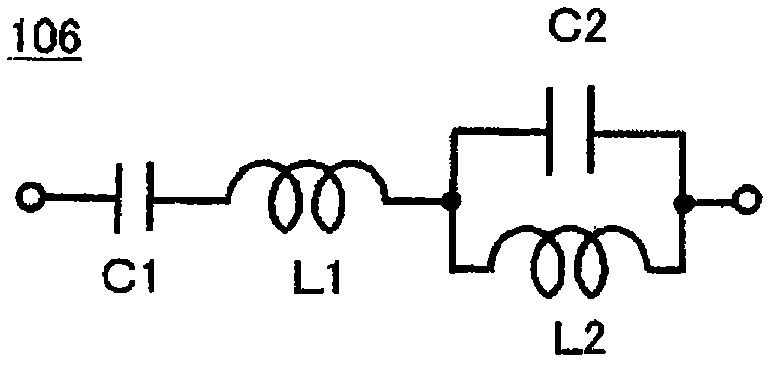
An antenna element (102) is provided with a first electricity-supplying port and a second electricity-supplying port, and is excited simultaneously through both the electricity-supplying ports so as to operate simultaneously as a first antenna section and a second antenna section, corresponding to each of the electricity-supplying ports. The antenna element (102) is excited by either a first frequency, or a second frequency that is higher than the first frequency. An antenna device is provided with: a slit (105) that generates isolation between the electricity-supplying ports; a trap circuit (106) that generates isolation at the slit (105) at the first frequency or the second frequency, when the antenna element (102) is excited by the first frequency or the second frequency; and a reactance element (107) that shifts the frequency at which the slit (105) generates isolation between the electricity-supplying ports to the first frequency, when the antenna element (102) is being excited by the first frequency.

Description

technical field [0001] The present invention mainly relates to an antenna device for mobile communication such as a mobile phone and a wireless communication device including the antenna device. Background technique [0002] The miniaturization and thinning of mobile communication wireless devices such as mobile phones are rapidly progressing. In addition, mobile wireless communication devices are used not only as conventional telephones but also as data terminals for transmitting and receiving e-mails, browsing WWW (World Wide Web, World Wide Web) pages, and the like. The information to be processed has also changed from voice and text information in the past to photographs and moving images. To achieve a larger capacity, further improvement in communication quality is required. In addition, mobile wireless communication devices need to be compatible with various applications such as voice calls as telephones, data communications for web browsing, and viewing of television...

Claims


Application Information

Patent Timeline
Patent Type & Authority Applications(China)
IPC IPC(8): H01Q21/30H01Q1/24H01Q13/08H01Q21/28H01Q1/52H01Q5/00H01Q5/10H01Q5/321
CPCH01Q9/0442H01Q9/0421H01Q5/0048H01Q5/0034H01Q1/243H01Q5/321H01Q5/35
Inventor 天利悟山本温坂田勉
Owner PANASONIC INTELLECTUAL PROPERTY CORP OF AMERICA
Learn More