Non-porous magnetic code lock and key

A magnetic code and key technology, used in keys, building locks, non-mechanical transmission-operated locks, etc., can solve the problems of repeated rotation, the inability to practically apply the volume of the lock body and the amount of keys, and achieves reduced volume and no external Magnetic leakage, small size effect

Inactive Publication Date: 2011-09-14
王国栋
View PDF5 Cites 2 Cited by
  • Summary
  • Abstract
  • Description
  • Claims
  • Application Information

AI Technical Summary

Problems solved by technology

In the actual use of this lock design, there is another problem, that is, because the steel balls swim in a large annular space, the key magnets and steel balls between adjacent annular spaces affect each other, and each time the lock is unlocked, it must be rotated repeatedly Keys, often require multiple attempts to open
Due to the above deficiencies, the lock with the structure described in the above patent can only be used for industrial valve locks, and the lock body must be removed from the valve before the valve can be operated in actual application, which cannot be practically applied to such as door locks, padlocks, Bicycle locks, motorcycle locks and other occasions that require the volume of the lock body and the number of keys

Method used


Image

  • Non-porous magnetic code lock and key
  • Non-porous magnetic code lock and key
  • Non-porous magnetic code lock and key

Examples


specific Embodiment approach

[0036] DETAILED DESCRIPTION OF THE PREFERRED EMBODIMENTS The present invention will be further described below in conjunction with the accompanying drawings:

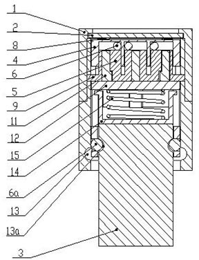
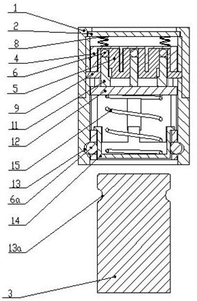
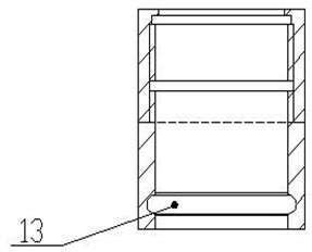
[0037] figure 1 It is a structural schematic diagram of the present invention, which provides a structural schematic diagram of a magnetic code lock in a locked state, figure 2 It is a structural schematic diagram of the present invention in an unlocked state, image 3 It is a structural schematic diagram of the lock housing in the present invention, Figure 4 It is a structural schematic diagram of the lock head in the present invention. combine figure 1 , figure 2 , image 3 , Figure 4 As shown, the non-porous magnetic code lock includes a lock casing, a lock cylinder, a lock machine and a lock head. The shape of the lock case 1 is a circular cylinder, and the upper end is equipped with an anti-drilling plate 2. There is a certain gap between the anti-drilling plate 2 and the lock case 1. The anti-drilling ...


PUM


Abstract

The invention relates to a non-porous magnetic code lock, and a key mated with the non-porous magnetic code lock for use, wherein the lock comprises a lock shell, a lock cylinder, a lock machine and a lock head, wherein the lock cylinder consists of a domain board, domain columns, a first steel ball, a support plate and a tappet; the lock machine and the lock head are formed by a second steel ball, a cylindrical ball rack and a cylindrical baffle; and the key comprises an outer shell, a main board, a key core and a magnetic. In the non-porous magnetic code lock and the key, the movement range of the first steel ball is limited by a hole in the domain board and a space formed by the domain columns, so that the movement area of the first steel ball is reduced, and the volume of the lock is effectively reduced; by reasonably designing the shape, the outer diameter, the arrangement manner and the distance of the domain columns and the key hole, code position is added, secrete key quantity exceeds eight hundred thousand, the produced lock and key have small volumes, and are convenient to carry; the lock is not limited by the installation space of an installation site, can be applied to a door lock, a padlock, a bicycle lock, a motorcycle lock, a luggage lock, a door lock for an electric equipment cabinet, even a bottle cap lock, thus having wide application range; and the designed key is matched with a key sheath, thus being convenient to use, and having no magnetic leakage to outside.

Description

technical field [0001] The invention relates to a magnetic lock, in particular to a non-porous magnetic code lock and a key used in conjunction with it. Background technique [0002] The keyholes of most of the locks sold on the market are open. Although the keyholes of a small number of locks are closed, objects other than their own keys can still be inserted into the keyholes, which can easily cause the keyholes of the locks to be blocked. Blocked or drilled, resulting in locks are often destroyed. With the continuous progress of science, magnetic locks and non-hole locks have come into people's lives, but because these locks contain magnets, they are easily cracked and opened, and there are some unsafe factors in using these locks. Chinese patent 2003201116144 provides a kind of non-porous magnetic control lock, this lock does not have lock hole, does not have magnet in the lock, and its structure is made up of lock core and lock shell, and lock core is made up of lock c...

Claims


Application Information

Patent Timeline
Patent Type & Authority Applications(China)
IPC IPC(8): E05B47/00E05B19/26E05B17/20E05B15/00
Inventor 王国栋杜道平
Owner 王国栋
Why Eureka
Try Eureka