Ammonia spraying grate and adjusting method thereof

A technology of ammonia injection grid and adjustment method, which is applied in separation methods, chemical instruments and methods, and separation of dispersed particles. It can solve the problems of large adjustment dead zone, slow flow rate change, and high adjustment requirements, and achieve the adjustment range without dead ends. area, to achieve the effect of flow size and flow change continuous

Inactive Publication Date: 2012-12-26
SOUTHEAST UNIV
View PDF5 Cites 2 Cited by
  • Summary
  • Abstract
  • Description
  • Claims
  • Application Information

AI Technical Summary

Problems solved by technology

[0003] The ammonia injection grid in the prior art adopts the method of opening a certain number and diameter of small holes on the metal round pipe, and its flow regulation depends on the regulating valve. Due to the limitation of the characteristic of the regulating valve itself, there is a large regulating dead zone. When the opening degree is small, the flow rate changes very slowly, and when the opening degree is large, the flow rate change is extremely fast, and there are great difficulties in the adjustment of the regulating valve, and the adjustment is extremely insensitive; on the other hand, in order to achieve a specific efficiency, There are extremely high requirements for the mixing of ammonia and flue gas. Usually, the standard deviation on the upper surface of the catalyst is required to be less than 5%, and the requirements for adjustment are relatively high.
Therefore, in the existing technology, it is extremely difficult to adjust when the boiler is under low load or high load, and the amount of denitrification catalyst has to be increased to meet the requirements during design, thereby increasing the investment cost

Method used


Image

  • Ammonia spraying grate and adjusting method thereof
  • Ammonia spraying grate and adjusting method thereof
  • Ammonia spraying grate and adjusting method thereof

Examples


Embodiment Construction

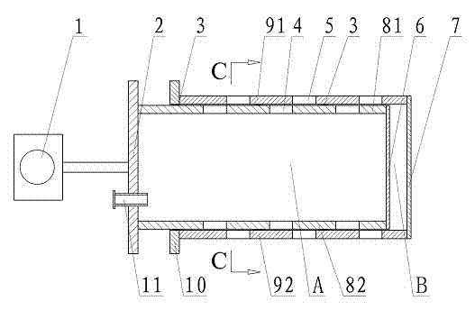
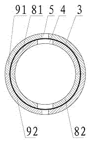
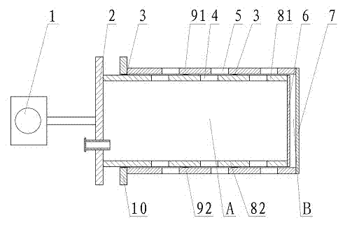
[0018] see Figure 1~3 As shown, the ammonia spray grid includes an upper outer sleeve 91, a lower outer sleeve 92 opposite to the upper outer sleeve 91, an upper inner sleeve 81 nested in the upper outer sleeve 91, and an upper inner sleeve 81 nested in the lower outer sleeve 92. Inside the lower inner casing 81.

[0019] One end of the upper outer casing 91 and the lower outer casing 92 is connected through the outer casing cover plate 7, and the other end of the upper outer casing 91 and the lower outer casing 92 is provided with an outer casing flange 10; the upper inner casing 81 and the lower inner casing One end of 82 is connected by inner casing cover plate 6, and the other end of upper inner casing 81 and lower inner casing 82 is provided with inner casing flange 2, upper inner casing 81, lower inner casing 82, inner casing The cover plate 6 and the inner sleeve flange 2 form a cavity A; there is a gap B between the inner sleeve cover plate 6 and the outer sleeve cov...


PUM


Abstract

The invention discloses an ammonia spraying grate and an adjusting method thereof, and relates to an ammonia spraying grate device for selective catalytic reduction (SCR) smoke denitrification device for tail gas of a thermal generator set boiler, a Garbage incineration device, a diesel engine and the like. The ammonia spraying grate comprises an upper outer sleeve (91), a lower outer sleeve (92) opposite to the upper outer sleeve (91), an upper inner sleeve (81) embedded in the upper outer sleeve (91), and a lower inner sleeve (82) embedded in the lower outer sleeve (92); one end of the upper outer sleeve (91) is connected with one end of the lower outer sleeve (92) through an outer sleeve cover plate (7); the other ends of the upper outer sleeve (91) and the lower outer sleeve (92) are provided with outer sleeve flanges (10). The adjusting method for the ammonia spraying grate comprises the following step of: adjusting the stroke of an actuating mechanism (1) step by step to make the upper inner sleeve (81) and the lower inner sleeve (82) gradually slide to the outer sleeve cover plate (7) and a gap (B) gradually change small, so that the overlapped area of a first small hole (4) and a second small hole (5) is gradually increased to adjusting the flow rate of mixed gas sprayed through the second small hole (5).

Description

technical field [0001] The invention relates to an ammonia spraying grille device used for selective catalytic reduction (SCR) flue gas denitrification devices of boilers of thermal power generation units, garbage incineration devices and diesel engines, etc., and belongs to the technical field of environmental protection equipment. Background technique [0002] China is a country where coal is the main energy source. Coal accounts for 75% of the primary energy, of which more than 84% is utilized through combustion. Nitrogen oxides (NOx) in the exhaust gas released by coal combustion is one of the main sources of air pollution. Selective catalytic reduction is the most common and effective method for removing nitrogen oxides from boiler tail gas, and is widely used in various industrial devices. The main principle is to use liquid ammonia or ammonia water as a reducing agent, mix it with air and spray it into the flue upstream of the SCR reactor, and react with nitrogen oxi...

Claims


Application Information

Patent Timeline
Patent Type & Authority Patents(China)
IPC IPC(8): B01D53/79B01D53/86B01D53/56
Inventor 徐海涛周长城沈凯
Owner SOUTHEAST UNIV
Why Eureka
Try Eureka