Parameter adjustable type polishing clamp device for heavy-calibre plane optical element
What is Al technical title?
Al technical title is built by PatSnap Al team. It summarizes the technical point description of the patent document.
A technology for optical components and polishing fixtures, applied in optical surface grinders, grinding/polishing equipment, manufacturing tools, etc., can solve problems such as uncertainty, low processing efficiency, and uncontrollable pressure in the contact area between components and polishing pads. Achieve the effect of fine control range, large control range and high material removal rate
Inactive Publication Date: 2012-10-10
XIAMEN UNIV
View PDF0 Cites 0 Cited by
Summary
Abstract
Description
Claims
Application Information
AI Technical Summary
This helps you quickly interpret patents by identifying the three key elements:
Problems solved by technology
Method used
Benefits of technology
Problems solved by technology
[0003] The purpose of the present invention is to provide a simple and practical parameter-adjustable large-diameter optical element for traditional annular polishing processing of large-diameter planar optical elements, the uncontrollability and uncertainty of the pressure in the contact area between the element and the polishing pad, and low processing efficiency. Aperture Plane Optical Component Polishing Fixture
Method used
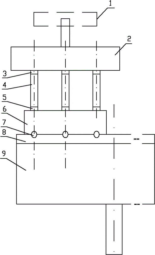
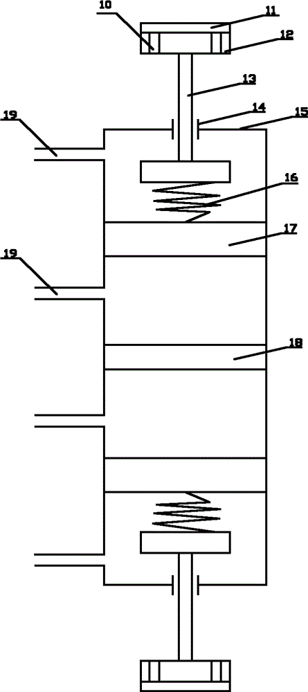
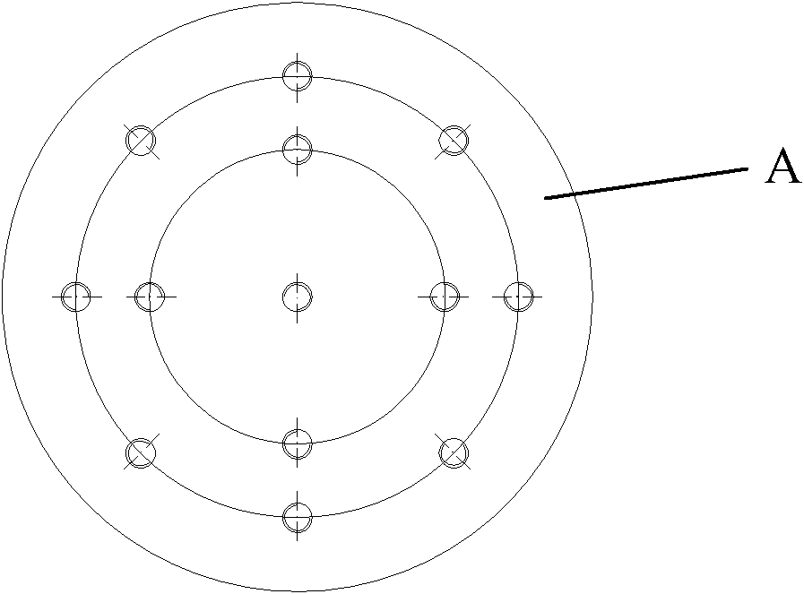
Image
Click on the blue label to locate the original text in one second.
Reading with bidirectional positioning of images and text.
Examples
Embodiment Construction
[0015] The present invention will be further described below in conjunction with the accompanying drawings.
[0016] see figure 1 , figure 1 The middle polishing pad 8 and the polishing disc 9 are symmetrical, only the left part is drawn, not all of them are drawn, and a part is omitted. The mass block 1 can be inserted through the central axis of the upper surface of the fixture plate 2 according to processing requirements. The sensor 7 is embedded in the polishing pad 8, and the pressure signal is input to the data acquisition card after passing through the servo amplifier, and the data acquisition card is installed on the industrial computer. According to the collected pressure data, it is compared with the pressure applied to each part of the component surface by the upper hydraulic piston device and the lower hydraulic piston device at the initial design stage, and the hydraulic pressure is adjusted through the hydraulic oil delivery and oil return device to change the ...
PUM
Abstract
The invention provides a parameter adjustable type polishing clamp device for a heavy-calibre plane optical element, relating to a polishing clamp device. The polishing clamp device comprises a mass block, a clamp flat plate, an upper hydraulic piston device, a lower hydraulic piston device, a hydraulic oil transmission and return device, a pressure sensor, a servo magnifier and an industrial personal computer, wherein the mass block is sleeved in a center shaft on the upper surface of the clamp flat plate, the upper hydraulic piston device and the lower hydraulic piston device are separated by a partition plate, are respectively adsorbed on the lower surface of the clamp flat plate and an upper surface of a workpiece by adsorption base membranes, and are respectively provided with a hydraulic cylinder, hydraulic oil, a piston, a push rod, a sealing ring, a spring, an oil transmission hole and an oil return hole, wherein the lower end of the push rod is connected with the piston through the spring, the upper end of the push rod is connected with a basic body of each adsorption base membrane, the oil transmission hole and the oil return hole are connected with an oil transmission hole and an oil return hole of the hydraulic oil transmission and return device, the sensor is embedded in a polishing gasket, the pressure signals of the sensor are put into a data acquisition card after passing through the servo amplifier, and the data acquisition card is installed on the industrial personal computer. The polishing clamp device is simple and practical in structure.
Description
technical field [0001] The invention relates to a polishing jig device, in particular to a parameter-adjustable polishing jig device for large-diameter flat optical elements. Background technique [0002] At present, how to realize high-efficiency batch processing of high-precision large-aperture optical components, especially large-aperture planar components, is an important issue in the field of optical manufacturing. After rough grinding, fine grinding or precision grinding, large-aperture planar optical components are required to be polished to improve surface accuracy and reduce surface roughness and subsurface defects. At present, the development of optical component polishing technology has made great progress, but for large-diameter planar optical components, especially for large-diameter planar optical components with a size of not less than 430mm×430mm, the progress is not great. The uncontrollability and uncertainty of the pressure in the contact area of optica...
Claims
Application Information
Patent Timeline
Application Date:The date an application was filed.
Publication Date:The date a patent or application was officially published.
First Publication Date:The earliest publication date of a patent with the same application number.
Issue Date:Publication date of the patent grant document.
PCT Entry Date:The Entry date of PCT National Phase.
Estimated Expiry Date:The statutory expiry date of a patent right according to the Patent Law, and it is the longest term of protection that the patent right can achieve without the termination of the patent right due to other reasons(Term extension factor has been taken into account ).
Invalid Date:Actual expiry date is based on effective date or publication date of legal transaction data of invalid patent.