
Backlight module, over-temperature protective circuit and over-temperature protective method

A technology of over-temperature protection and backlight module, which is applied in the direction of instruments and static indicators, etc. It can solve the problems of affecting the user's visual perception, affecting the conversion efficiency of DC-DC converter 110, backlight flickering, etc., to reduce the temperature and reduce the current , the effect of a simple circuit

Inactive Publication Date: 2014-02-26
CPTF VISUAL DISPLAY (FUZHOU) LTD +1
View PDF5 Cites 0 Cited by
  • Summary
  • Abstract
  • Description
  • Claims
  • Application Information

AI Technical Summary

Problems solved by technology

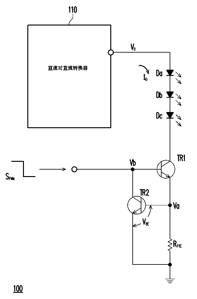
Although the above-mentioned over-temperature protection circuit can achieve the effect of over-temperature protection, due to its architecture design, the thermistor R PTC The generated power consumption will affect the conversion efficiency of the DC-to-DC converter 110
Moreover, the above-mentioned over-temperature protection circuit protects the light-emitting diodes Da~Dc by turning off the transistor TR1, so that the light-emitting diodes Da~Dc may switch between light-emitting and non-light-emitting, so the phenomenon of backlight flickering may occur, which affects the user's visual perception

Method used


Image

  • Backlight module, over-temperature protective circuit and over-temperature protective method
  • Backlight module, over-temperature protective circuit and over-temperature protective method
  • Backlight module, over-temperature protective circuit and over-temperature protective method

Examples


Embodiment Construction

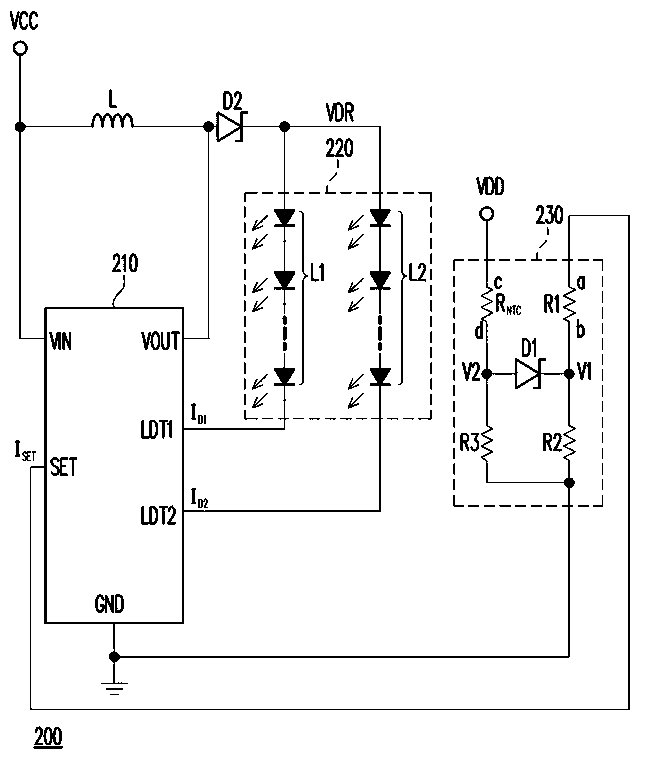
[0050] figure 2 It is a system diagram of a backlight module according to an embodiment of the present invention. Please refer to figure 2 , in this embodiment, the backlight module 200 includes at least a light source driver 210 , a light emitting component 220 and an over-temperature protection circuit 230 . The light source driver 210 has a voltage input terminal VIN, a voltage output terminal VOUT, a ground terminal GND, a current setting terminal SET and at least one light source drive terminal (such as LDT1 and LDT2), wherein the number of light source drive terminals is determined by the circuit structure of the light emitting component 220.

[0051] In the light source driver 210, the voltage input terminal VIN receives the system voltage VCC, the voltage output terminal VOUT outputs the driving voltage VDR to the light emitting component 220, and the current setting terminal SET receives the set current I SET , the ground terminal GND is coupled to the ground ...


PUM


Abstract

The invention relates to an over-temperature protective circuit which is suitable for being coupled with a light source driver of a light-emitting assembly. The light source driver is provided with a current setting end which is used for receiving a setting current so as to correspondingly control the current flowing through the light-emitting assembly. The over-temperature protective circuit comprises a first resistor, a second resistor, a third resistor, a thermistor and a diode, wherein the first end of the first resistor is coupled with the current setting end for supplying the setting current; the second resistor is coupled between the second end of the first resistor and a grounding voltage; the first end of the thermistor is coupled with a reference voltage and the thermistor is used for measuring the temperature of the light-emitting assembly; the third resistor is coupled between the second end of the thermistor and the grounding voltage; and the positive pole of the diode is coupled with the second end of the thermistor, and the negative pole of the diode is coupled with the second end of the first resistor.

Description

technical field [0001] The invention relates to a backlight module, an over-temperature protection circuit and an over-temperature protection method thereof, and in particular relates to a backlight module, an over-temperature protection circuit and an over-temperature protection method using a light-emitting diode as a backlight source. Background technique [0002] With the increasing development of the electronic industry, flat panel displays have gradually replaced cathode ray tube displays and become the mainstream of current displays. Among the flat panel displays, the liquid crystal display technology is the most mature and popular. However, since the liquid crystal display panel of the liquid crystal display itself cannot emit light, a backlight module must be disposed under the liquid crystal display panel to provide a light source to achieve the display function. Moreover, since light emitting diodes (Light Emitting Diodes, LEDs) have the characteristics of long l...

Claims


Application Information

Patent Timeline
Patent Type & Authority Patents(China)
IPC IPC(8): G09G3/34G09G3/36
Inventor 邱坤麒陈昀至
Owner CPTF VISUAL DISPLAY (FUZHOU) LTD
Learn More