Eureka AIR delivers breakthrough ideas for toughest innovation challenges, trusted by R&D personnel around the world.

Later-stage processing method of fabric and special equipment thereof

A technology of special equipment and processing methods, applied in the processing of textile materials, textile and papermaking, fabric surface trimming, etc., can solve the problems of inability to open and flatten, unable to enter the drying tunnel in the weft direction, and unpredictable dimensions in the weft direction. Achieve the effect of avoiding uneven feeding

Active Publication Date: 2011-08-31
嘉兴好事帮医疗器械有限公司
View PDF4 Cites 5 Cited by
  • Summary
  • Abstract
  • Description
  • Claims
  • Application Information

AI Technical Summary

Problems solved by technology

[0002] In the current dyeing and finishing equipment, the methods and machines usually used are suitable for dyeing and finishing of non-elastic fabrics. When finishing elastic fabrics, especially high-elastic fabrics, it includes dyeing, washing, drying and setting. , often can not be handled: because warp elastic fabric or two-way warp and weft elastic fabric will be deformed after entering water, the size will be reduced, and the size and elasticity cannot be fixed when drying; In the existing technology, rope-like cloth feeding is generally used, that is, the elastic cloth is twisted into a rope shape and sent into the machine. However, if rope-like cloth feeding is used for dyeing, when the fabric is opened, the fabric must be flattened, resulting in uneven dyeing; The elastic force in the weft direction cannot be controlled, and the weft direction cannot enter the drying tunnel, and after the rope-like knot, the weft direction size can no longer be estimated; and it may no longer be possible to open and make flat
The existing technology and equipment all use the method of warp and weft two-way force traction to make the fabric flat. Using this method must face the problem of uncontrollable tension, because first, the weft shrinkage rate of the elastic fabric after water entry cannot be predicted, so it cannot be adjusted. Determine the tensile strength and size of the weft direction; the second is that the warp direction will become shorter, because all the existing downstream equipment is in the form of tension traction. When the fabric is conveyed, the fabric is also completely pulled apart. Or other drying methods, the fabric is shaped and no longer elastic. That is to say, if the size of the fabric is fixed by increasing the tension in the warp and weft directions, then the elasticity will not be controlled, and the elasticity of the fabric will be damaged.

Method used


Image

  • Later-stage processing method of fabric and special equipment thereof
  • Later-stage processing method of fabric and special equipment thereof
  • Later-stage processing method of fabric and special equipment thereof

Examples


Embodiment 1

[0039] See figure 1 , what the equipment of this embodiment adopts is single-cylinder to carry out the treatment with water, and overall equipment comprises cylinder body 1, cylinder inlet device 2, cylinder outlet device 3, expansion device, ironing machine 4, transmission chain 6, sliding pressure roller 7 .

[0040] The cylinder inlet and the cylinder outlet of the cylinder body 1 are respectively provided with a cylinder inlet device 2 and a cylinder outlet device 3; the cylinder inlet device 2 and the cylinder outlet device 3 are respectively two pressure rollers 5 arranged up and down and a driving roller 5; the pressure water roller 5 of the cylinder discharge device 3 is a sponge water absorption roller; the ironing machine 4 includes a first cylinder 41 and a second cylinder 42 with adjustable gear ratios; It is arranged on the conveyor belt at the feeding port of the first cylinder 41 of the ironing machine 4 . Transmission chain 6 is arranged on the bottom of cyli...

Embodiment 2

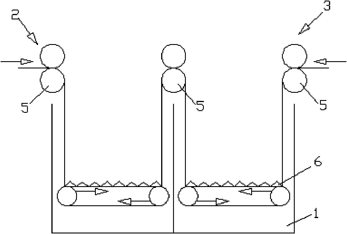
[0043] See figure 2 , This embodiment is basically the same as Embodiment 1, except that it also includes two pressure water rollers 5 arranged up and down above the sub-axis in the cylinder body 1 . This single cylinder with water treatment can be merged by existing 2 common single cylinders, also can be to increase pressure water roller 5 in the middle part of longer single cylinder, can handle longer cloth 8 like this.

Embodiment 3

[0045] See image 3 , the equipment of this embodiment uses a plurality of cylinders 1 to carry out water treatment, and the rest of the equipment is the same as that of Embodiment 1. Three cylinders 1 are shown in the figure, and the cylinder inlet and outlet of each cylinder 1 are respectively provided with a cylinder inlet device 2 and a cylinder outlet device 3 , and a circulating transmission chain 6 is arranged at the bottom of the cylinder body 1 . The pressure water roller 5 of 2 cylinder outlet devices 3 of each cylinder inlet device all uses sponge suction roller, can obtain better coloring or cleaning effect like this.

[0046] The continuous fabric is treated with water in multiple cylinders, and the cloth head of the fabric 8 is smoothly passed through the middle of the two pressure rollers 5 at the inlet of the first cylinder body 1, and the power device of each pressure roller 5 is started. Set the speed ratio of each transmission chain 6 so that the cloth 8 fa...


PUM


Abstract

The invention discloses a later-stage processing method of fabric and special equipment thereof. The special equipment comprises one or a plurality of cylinders, an expander and an ironing machine which are arranged in sequence along the running direction of the fabric, wherein an inlet device and an outlet device are arranged at the inlet and outlet of each cylinder respectively; each inlet device and each outlet device respectively comprise an upper pressurized water roll, a lower pressurized water roll and a power device used for driving the pressurized water rolls; a sponge water absorbing roll is adopted as the pressurized water roll of the final outlet device; the ironing machine comprises a first rotary drum and a second rotary drum the gear ratios of which can be adjusted; and the expander takes the shape of an inverted trapezoid, and is arranged on a conveyer belt at the feeding port of the first rotary drum of the ironing machine. The special equipment disclosed by the invention can be used for simultaneously processing elastic fabric and non-elastic fabric, and the processed elastic fabric has flat and smooth surface and good elasticity.

Description

technical field [0001] The invention relates to a cloth post-processing method and special equipment used in the post-processing. Background technique [0002] In the current dyeing and finishing equipment, the methods and machines usually used are suitable for dyeing and finishing of non-elastic fabrics. When finishing elastic fabrics, especially high-elastic fabrics, it includes dyeing, washing, drying and setting. , often can not be handled: because warp elastic fabric or two-way warp and weft elastic fabric will be deformed after entering water, the size will be reduced, and the size and elasticity cannot be fixed when drying; In the existing technology, rope-like cloth feeding is generally used, that is, the elastic cloth is twisted into a rope shape and sent into the machine. However, if rope-like cloth feeding is used for dyeing, when the fabric is opened, the fabric must be flattened, resulting in uneven dyeing; The elastic force in the weft direction cannot be cont...

Claims


Application Information

Patent Timeline
Patent Type & Authority Applications(China)
IPC IPC(8): D06C27/00D06C15/02D06B23/00
Inventor 韩士兵
Owner 嘉兴好事帮医疗器械有限公司
Why Eureka
Eureka Blog
Learn More