
Soft abrasive particle flow constraint runner device

A technology that constrains the flow channel and the flow of abrasive particles. It is applied in the direction of grinding/polishing equipment. It can solve the problems of long processing flow channel, small number of abrasive particles, and clogging of abrasive particles, so as to achieve engineering, improve processing efficiency, The effect of preventing clogging of the flow path

Active Publication Date: 2013-07-24
海宁市黄湾镇资产经营有限公司
View PDF4 Cites 2 Cited by
  • Summary
  • Abstract
  • Description
  • Claims
  • Application Information

AI Technical Summary

Problems solved by technology

Based on the previous experimental conditions, the single constraint module design and the simple single-input, single-output processing channel have the following disadvantages: ①The viscosity of the abrasive particle flow is too high and the effect of the constraint module is not obvious, resulting in an excessively large boundary layer, turbulent flow effects and The flow disorder of abrasive grains near the surface of the workpiece is not obvious, and the number of abrasive grains involved in processing is too small. After a period of processing, streaks appear on the surface of the workpiece, which does not achieve the desired effect; ②The velocity of the fluid at the inlet of the flow channel reaches or Exceeds the minimum speed for generating turbulent flow, but due to the long processing flow channel, energy loss during the flow process, turbulent kinetic energy decreases, and the abrasive particle flow is basically in a laminar flow state in the rear part and edge part of the workpiece, resulting in the processing of the latter part of the workpiece The effect is not obvious, resulting in uneven processing effect on the entire workpiece processing surface
③ After processing for a period of time, open the restricted flow channel and you will find that there is abrasive particle deposition and clogging

Method used


Image

  • Soft abrasive particle flow constraint runner device
  • Soft abrasive particle flow constraint runner device
  • Soft abrasive particle flow constraint runner device

Examples


Embodiment 1

[0037] refer to Figure 1-8 , Figure 11 , 12

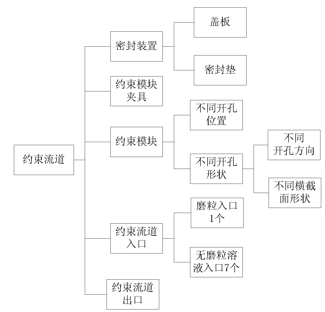
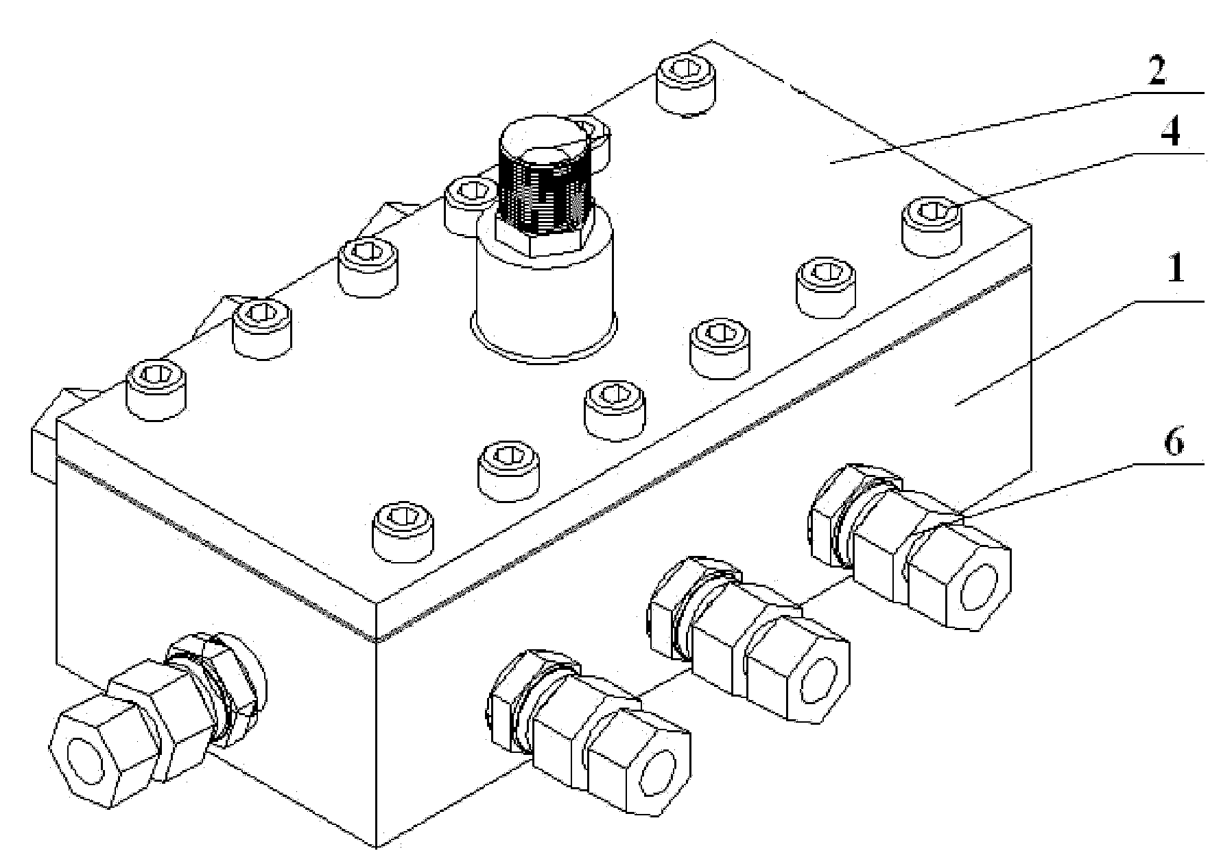
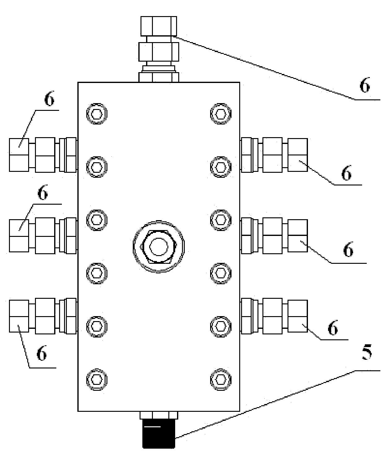
[0038] The soft abrasive particle flow restricting flow channel device includes a base 1 with a processing flow channel 11 inside and a cover plate 2 covering the base 1. The bottom plate of the base 1 is provided with a workpiece sink for accommodating workpieces to be processed 12. The top of the processing channel 11 is provided with a sealing sinker 13, and the sealing sinker 13 is provided with a sealing gasket 14 matching it;

[0039] The processing channel 11 is provided with a constraint module 3 and a fixture 4 for fixing the constraint module 3, the abrasive fluid impacts the workpiece to be processed through the constraint module 3, and the constraint module 3 is provided with an inclined passage for allowing the abrasive fluid to pass through. hole 31;

[0040] The cover plate 2 is connected to the base 1 through bolts 4, and the bottom of the cover plate 2 is provided with a boss 21 that is adapted to the gasket ...

Embodiment 2

[0070] refer to Figure 9 , 10

[0071] The difference between this embodiment and the first embodiment lies in that a pair of inclined through holes 31 are symmetrically opened on the constraining module 3 , and the cross section of the through holes 31 is triangular.


PUM


Abstract

The invention discloses a soft abrasive particle flow constraint runner device, which comprises a base and a cover plate, wherein the base is provided with a workpiece sinking tank; the top of a processing runner is provided with a sealed sinking tank; a sealing gasket matched with the sealed sinking tank is arranged inside the sealed sinking tank; a constraint module and a clamp for fixing the constraint module are arranged inside the processing runner; abrasive particle fluid impacts a workpiece to be processed through the constraint module, and a through hole is formed on the constraint module; the cover plate is connected with the base through a bolt, and a lug boss is formed at the bottom of the cover plate; a plurality of runner holes which allow abrasive particle-free fluid to flowinto the processing runner are formed on the base, wherein one runner hole is connected with a pipeline interface which allows fluid in the processing runner to flow out so as to form a drainage port, and the rest runner holes are connected with a one-way valve which prevents the fluid which is being processed from returning; and an abrasive particle flow inlet which allows fluid mixed with abrasive particles to enter the processing runner is formed on the cover plate, and the abrasive particle flow inlet is connected with the one-way valve. The device has the advantages of having good processing effect and high processing efficiency and avoiding non-uniform processing effect.

Description

technical field [0001] The invention relates to a soft abrasive flow restricting channel device. technical background [0002] Although the traditional polishing method can achieve high precision, it cannot process the surface that the polishing tool cannot reach, such as structured surfaces such as grooves, grooves, holes, prisms, pyramids, and narrow slits involved in mold manufacturing. Liquid-solid two-phase soft abrasive flow processing is the application of soft abrasive flow to form turbulent flow on the structured surface of the workpiece to be processed, coupled with a constraint module, so that the processed surface becomes a part of the flow channel wall to form abrasive flow When the abrasive grains flow through the channel, the rough part of the wall is cut, realizing the toolless precision machining of the structured surface. [0003] The base design of the processing flow channel, the design and installation of the restricted flow channel and the restricted m...

Claims


Application Information

Patent Timeline
Patent Type & Authority Patents(China)
IPC IPC(8): B24C5/00
Inventor 张利池永为谭大鹏计时鸣
Owner 海宁市黄湾镇资产经营有限公司
Learn More