Bucket wheel excavator

A technology for excavators and bucket wheels, applied in the direction of mechanically driven excavators/dredgers, etc., can solve the problems of waste of manpower and material resources, low degree of mechanization, and unsatisfactory satisfaction

Active Publication Date: 2011-08-10
大连重工通用设备有限责任公司
View PDF4 Cites 17 Cited by
  • Summary
  • Abstract
  • Description
  • Claims
  • Application Information

AI Technical Summary

Problems solved by technology

[0002] In the past, excavator equipment was driven by a motor to drive a reducer. The energy conversion relationship is: electrical energy is converted into mechanical energy; Working in an environment with relatively good working conditions, which directly affects the limitations of equipment use, it is precisely because of such harsh working conditions that many advanced equipment cannot enter this area for construction, resulting in these areas The construction of the engineering work can only adopt the original operation method, such as using a single bucket excavator to excavate and use a car to reload, or use a train to reload, which causes a lot of waste of manpower and material resources, and high energy consumption and low production capacity. , the degree of mechanization is low; in the past, when the driving device of the excavator equipment was overloaded, the traditional transmission mode would cause overcurrent of the motor, tripping of the motor, broken teeth of the gear, accidental damage of the motor, and damage of some steel structures due to overload, etc. Although the traditional The transmission method is protected by torque-limiting couplings and other devices, but its reducer will still bear excessive loads, and the overload lasts for a long time, so that the mechanism and structure are always overloaded for a relatively long time, and the torque is limited. Couplings, hydraulic couplings, and motors generate heat, and the effect of traditional transmission methods on limiting overload is not very satisfactory; in addition, because the previous bucket wheel excavators were driven by electric motors, they could only work on land

Method used


Image

  • Bucket wheel excavator
  • Bucket wheel excavator
  • Bucket wheel excavator

Examples


Embodiment Construction

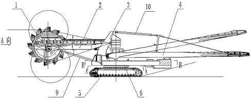
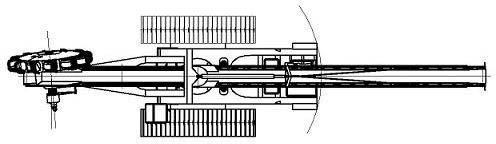
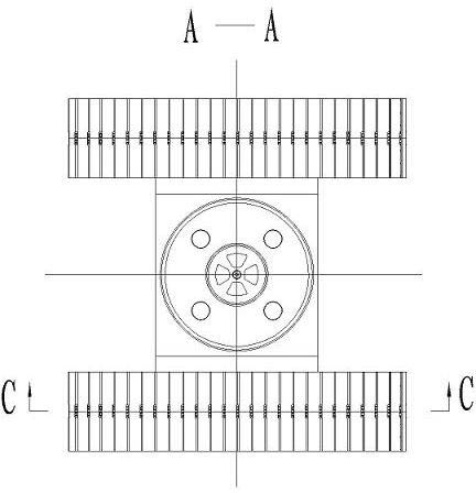
[0022] Such as figure 1 , figure 2 , image 3 , Figure 4 , as shown in Figure 5 and Figure 6, the bucket wheel excavator includes seven parts: bucket wheel mechanism 1, material receiving arm 2, L beam 3, discharge arm 4, walking mechanism, center large slewing 6 and center small slewing 7. The wheel mechanism 1 is installed on the front end of the material receiving arm 2, the rear end of the material receiving arm 2 is hinged on the upper part of the L beam 3, one end of the discharge arm 4 is supported on the central small swing 7, and the other end is connected to the top of the L beam 3 through a tie rod , the central large slewing 6 is installed between the L beam 3 and the central frame, the central small slewing 7 is installed on the central frame, the bucket wheel mechanism 1 is composed of a hydraulic motor 20, a bucket wheel reducer 21, a bucket wheel shaft 19, and a bucket wheel body 22 and a hopper, the bucket wheel shaft 19 is installed between the two beari...


PUM


Abstract

The invention discloses a bucket wheel excavator which comprises a bucket wheel mechanism, a material receiving arm, an L-beam, a discharging arm (4), a walking mechanism, a large central gyrator and a small central gyrator, wherein the bucket wheel mechanism is arranged at the front end of the material receiving arm; the back end of the material receiving arm is hinged on the upper part of the L-beam; one end of the discharging arm is supported on the small central gyrator, and the other end of the discharging arm is connected to the top of the L-beam through a pull rod; the large central gyrator is arranged between the L-beam and a central frame; the small central gyrator is arranged on the central frame; the bucket wheel mechanism consists of a hydraulic motor, a bucket wheel speed reducer, a bucket wheel shaft, a bucket wheel body and a hopper; the bucket wheel shaft is arranged between two bearing seats at the front end of the material receiving arm; the bucket wheel speed reducer and the hydraulic motor are arranged at one end of the bucket wheel shaft, and the bucket wheel body is arranged at the other end of the bucket wheel shaft; and the hopper is fixed on the bucket wheel body. A power system of the entire bucket wheel excavator adopts a full-hydraulic mode, is provided with an engine, does not need to be connected with power electricity, has high yield, a wide application field, low noise and low pollution, and is free and flexible.

Description

technical field [0001] The invention relates to the technical field of excavators, in particular to a bucket wheel excavator. Background technique [0002] In the past, excavator equipment was driven by a motor to drive a reducer. The energy conversion relationship is: electrical energy is converted into mechanical energy; Working in an environment with relatively good working conditions, which directly affects the limitations of equipment use, it is precisely because of such harsh working conditions that many advanced equipment cannot enter this area for construction, resulting in these areas The construction of the engineering work can only adopt the original operation method, such as using a single bucket excavator to excavate and use a car to reload, or use a train to reload, which causes a lot of waste of manpower and material resources, and high energy consumption and low production capacity. , the degree of mechanization is low; in the past, when the driving device o...

Claims


Application Information

Patent Timeline
Patent Type & Authority Applications(China)
IPC IPC(8): E02F3/18E02F3/24
Inventor 刘本兴付海滨杨伦宋小川刘震侯晓云
Owner 大连重工通用设备有限责任公司
Why Eureka
Try Eureka